Bus to Vector
Convert virtual bus to vector
Libraries:
Simulink /
Signal Attributes
HDL Coder /
Signal Attributes
Description
The Bus to Vector block converts a virtual bus to a vector. Use the Bus to Vector block only to replace an implicit bus-to-vector conversion with an explicit conversion.
Blocks that do not accept buses may implicitly convert buses to vectors. When a bus is
treated as a vector, bus elements become inaccessible. To identify and correct buses
used as vectors, use the Model Advisor check Check bus signals treated as
vectors or the function Simulink.BlockDiagram.addBusToVector.
Examples
To more easily identify unexpected conversions, specify acceptable bus-to-vector conversions with Bus to Vector blocks.
Open and simulate the example model.
mdl = "BusToVector";
open_system(mdl)
sim(mdl);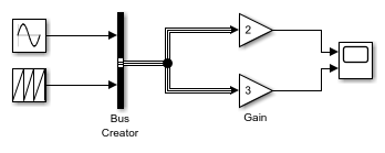
The model simulates correctly, but the input to the Gain block is a bus, while the output is a vector. The Gain block implicitly converts the bus to a vector.
To insert Bus to Vector blocks where blocks implicitly convert buses to vectors, use the Simulink.BlockDiagram.addBusToVector function with the third argument set to false.
When you use the Simulink.BlockDiagram.addBusToVector function with the third argument set to false, the function saves the model. To create a copy of the ex_bus_to_vector model, this example uses the save_system function.
mdl1 = "BusToVectorExplicit";
save_system(mdl,mdl1)

[blocks,busToVectors] = ...
    Simulink.BlockDiagram.addBusToVector(mdl1,true,false)
### Processing block diagram 'BusToVectorExplicit'
### Number of blocks left that are connected to a bus being used as a vector: 2
### Successfully inserted Bus to Vector Blocks in model. Preparing to save model and/or libraries
### To eliminate modeling errors in the future, please enable strict bus modeling by setting the 'Bus signal treated as vector' diagnostic in the Configuration parameter dialog, Diagnostic/Connectivity tab to 'error'
### Done processing block diagram 'BusToVectorExplicit'
blocks=1×2 struct array with fields:
    BlockPath
    InputPort
    LibPath
busToVectors = 2×1 cell
    {'BusToVectorExplicit/Bus to Vector' }
    {'BusToVectorExplicit/Bus to Vector1'}
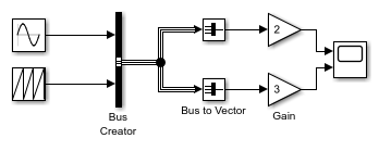
The Gain blocks no longer implicitly convert the buses to vectors. The inserted Bus to Vector blocks perform the conversions explicitly.
Ports
Input
Output
Block Characteristics
Data Types |
|
Direct Feedthrough |
|
Multidimensional Signals |
|
Variable-Size Signals |
|
Zero-Crossing Detection |
|
Tips
To identify buses treated as vectors during simulation, set the Bus signal treated as vector configuration parameter to
warningorerror. The default setting for Bus signal treated as vector isnone, which generates no warning or error message when a block implicitly converts a bus to a vector.If you use Save As to save a model to a Simulink® version before R2007a, a null subsystem that outputs nothing replaces each Bus to Vector block. Before you can use the model, reconnect or otherwise correct each path that used to contain a Bus to Vector block but now is interrupted by a null subsystem.