Logical Operator
Perform specified logical operation on input
Libraries:
Simulink /
Commonly Used Blocks
Simulink /
Logic and Bit Operations
HDL Coder /
Commonly Used Blocks
HDL Coder /
Logic and Bit Operations
Description
The Logical Operator block performs the specified logical operation on its
inputs. An input value is true (1) if it is nonzero and false
(0) if it is zero.
You select the Boolean operation connecting the inputs with the
Operator parameter list. If you select
rectangular as the Icon shape
property, the name of the selected operator displays on the block icon. If you select
distinctive as the Icon shape
property, the name of the selected operator does not display on the block icon. This
table shows supported operations:
| Operation | Description |
|---|---|
|
AND |
TRUE if all inputs are TRUE |
|
OR |
TRUE if at least one input is TRUE |
|
NAND |
TRUE if at least one input is FALSE |
|
NOR |
TRUE when no inputs are TRUE |
|
XOR |
TRUE if an odd number of inputs are TRUE |
|
NXOR |
TRUE if an even number of inputs are TRUE |
|
NOT |
TRUE if the input is FALSE |
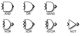
If you select distinctive as the Icon shape,
the block appearance indicates its function. Simulink® software displays a distinctive shape for the selected operator,
conforming to the IEEE® Standard Graphic Symbols for Logic Functions.
To specify the number of input ports, use the Number of input ports
parameter. The output type is specified using the Output data type
parameter. An output value is 1 if TRUE and 0 if
FALSE.
Note
The output data type should represent zero exactly. Data types that satisfy this condition include signed and unsigned integers, and any floating-point data type.
The size of the output depends on input vector size and the selected operator:
If the block has more than one input, any nonscalar inputs must have the same dimensions. For example, if any input is a 2-by-2 array, all other nonscalar inputs must also be 2-by-2 arrays.
Scalar inputs are expanded to have the same dimensions as the nonscalar inputs.
If the block has more than one input, the output has the same dimensions as the inputs (after scalar expansion) and each output element is the result of applying the specified logical operation to the corresponding input elements. For example, if the specified operation is AND and the inputs are 2-by-2 arrays, the output is a 2-by-2 array whose top left element is the result of applying AND to the top left elements of the inputs, and so on.
For a single vector input, the block applies the operation (except the NOT operator) to all elements of the vector. The output is always a scalar.
The NOT operator accepts only one input, which can be a scalar or a vector. If the input is a vector, the output is a vector of the same size containing the logical complements of the input vector elements.
When configured as a multi-input XOR gate, this block performs an addition modulo two operation as mandated by the IEEE Standard for Logic Elements.
Examples
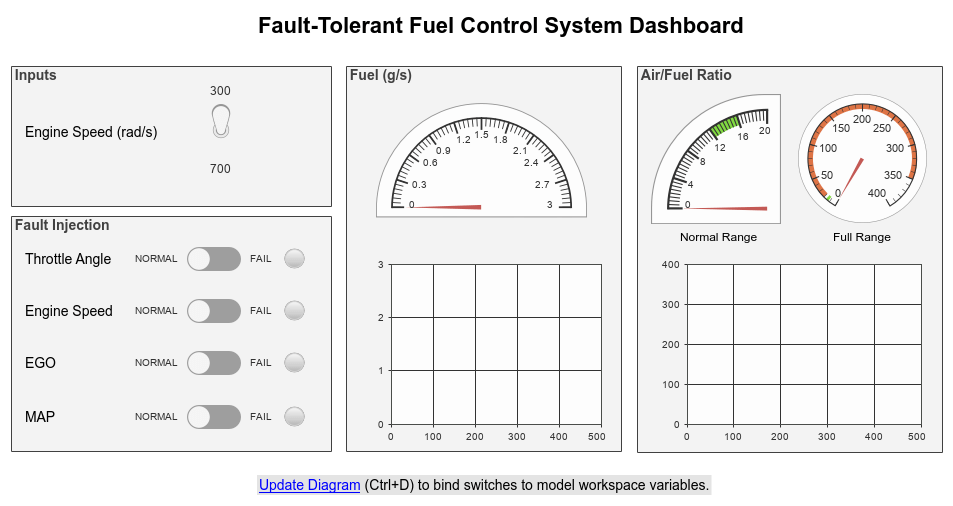
Model Fault-Tolerant Fuel Control System
Combine Stateflow® and Simulink® capabilities to model hybrid systems. This type of modeling is particularly useful for systems that have numerous possible operational modes based on discrete events. Traditional signal flow is handled in Simulink while changes in control configuration are implemented in Stateflow. The model described in this example represents a fuel control system for a gasoline engine. The system is robust in that it detects individual sensor failures, and the control system is dynamically reconfigured for uninterrupted operation.
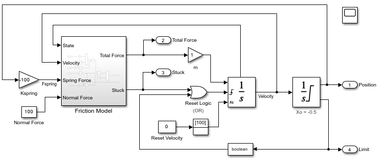
Model Stick-Slip Friction and Hard Stops in Mass-Spring-Damper System
One way you can incorporate hard stops and friction changes from stick-slip motion into a mass-spring-damper model.
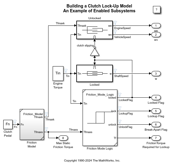
Building a Clutch Lock-Up Model
Use Simulink® to model and simulate a rotating clutch system. Although modeling a clutch system is difficult because of topological changes in the system dynamics during lockup, this example shows how enabled subsystem can easily handle such problems. We illustrate how to employ important Simulink modeling concepts in the creation of the clutch simulation. Designers can apply these concepts to many models with strong discontinuities and constraints that may change dynamically.
Ports
Input
Output
Parameters
Main
Select the logical operator to apply to block inputs.
AND— TRUE if all inputs are TRUEOR— TRUE if at least one input is TRUENAND— TRUE if at least one input is FALSENOR— TRUE when no inputs are TRUEXOR— TRUE if an odd number of inputs are TRUENXOR— TRUE if an even number of inputs are TRUENOT— TRUE if the input is FALSE
Programmatic Use
Block Parameter:
Operator |
| Type: character vector |
Values:
'AND' | 'OR' | 'NAND' | 'NOR' | 'XOR' | 'NXOR' |
'NOT' |
Default:
'AND' |
Specify the number of block inputs as a positive integer.
Programmatic Use
Block Parameter:
Inputs |
| Type: character vector |
| Values: positive integer |
Default:
'2' |
Dependencies
This parameter is not available when you set the
Operator to
NOT.
Specify the shape of the block icon.
rectangular— Results in a rectangular block that displays the name of the selected operator.distinctive— Use the graphic symbol for the selected operator as specified by the IEEE standard.
Programmatic Use
Block Parameter:
IconShape |
| Type: character vector |
Values:
'rectangular' | 'distinctive' |
Default:
'rectangular' |
Specify the time interval between samples. To inherit the sample time, set this
parameter to -1. For more information, see Specify Sample Time.
Dependencies
This parameter is visible only if you set it to a value other than
-1. To learn more, see Blocks for Which Sample Time Is Not Recommended.
Programmatic Use
To set the block parameter value programmatically, use
the set_param function.
| Parameter: | SampleTime |
| Values: | "-1" (default) | scalar or vector in quotes |
Data Type
To require that all block inputs and the output have the same data type, select this check box. When you clear this check box, the inputs and output can have different data types.
Programmatic Use
Block Parameter:
AllPortsSameDT |
| Type: character vector |
Values:
'off' | 'on |
Default:
'off' |
Specify the output data type. When you select:
boolean— The block output has data typeboolean.Inherit: Logical (see Configuration Parameters: Optimization)— The block uses the Implement logic signals as Boolean data configuration parameter to specify the output data type (see Implement logic signals as Boolean data (vs. double)).Note
This option supports models created before the
booleanoption was available. Use one of the other options, preferablyboolean, for new models.Inherit: Inherit via back propagation— The block inherits a data type. When you select this option, the output data type and scaling matches that of the next downstream block.fixdt(1,16)— The block output has the specified fixed-point data typefixdt(1,16).Tip
The Data Type Assistant helps you set data attributes. To use the Data Type Assistant, click
 . For more information, see Specify Data Types Using Data Type Assistant.
<data type expression>— The block output has the data type you specify as a data type expression, for example,Simulink.NumericType.Tip
To enter a built-in data type (
double,single,int8,uint8,int16,uint16,int32, oruint32), enclose the expression in single quotes. For example, enter'double'instead ofdouble.
Programmatic Use
Block Parameter:
OutDataTypeStr |
| Type: character vector |
Values:
'Inherit: Logical (see Configuration Parameters:
                        Optimization)'
| 'boolean' |
'fixdt(1,16)' | '<data type
expression>' |
Default:
'boolean' |
Select the category of data to specify.
Built in— Specifies built-in data types. SelectingBuilt inenablesboolean.Inherit— Specifies inheritance rules for data types. SelectingInheritenablesLogical (see Configuration Parameters: Optimization).Fixed point— Specifies fixed-point data types.Expression— Specifies expressions that evaluate to data types.
Dependencies
To enable this parameter, click the Show data type assistant button.
Select the data type override mode for this signal.
When you select
Inherit, Simulink inherits the data type override setting from its context, that is, from the block,Simulink.Signalobject or Stateflow® chart in Simulink that is using the signal.When you select
Off, Simulink ignores the data type override setting of its context and uses the fixed-point data type specified for the signal.
For more information, see Specify Data Types Using Data Type Assistant in the Simulink documentation.
Dependencies
To enable this parameter, set Mode to Built
in or Fixed point.
Tips
The ability to turn off data type override for an individual data type provides greater control over the data types in your model when you apply data type override. For example, you can use this option to ensure that data types meet the requirements of downstream blocks regardless of the data type override setting.
Specify whether you want the fixed-point data as signed or unsigned. Signed data can represent positive and negative values, but unsigned data represents positive values only. For more information, see Specifying a Fixed-Point Data Type.
Dependencies
To enable this parameter, set Mode to
Fixed point.
Specify the bit size of the word that holds the quantized integer. For more information, see Specifying a Fixed-Point Data Type.
Dependencies
To enable this parameter, set Mode to
Fixed point.
Specify the method for scaling your fixed-point data to avoid overflow conditions and
minimize quantization errors. Specifying Integer has the same
result as specifying a binary point location and setting the fraction length to
0.
Dependencies
To enable this parameter, click the Show data type
assistant button and set Mode to
Fixed point.
Block Characteristics
Data Types |
|
Direct Feedthrough |
|
Multidimensional Signals |
|
Variable-Size Signals |
|
Zero-Crossing Detection |
|