Programmatically Create Bus Element Ports
This example shows how to create and modify bus element ports using these functions:
add_block— Add In Bus Element and Out Bus Element blocks to represent bus element ports.set_param— Specify values for the block parameters, port attributes, and element attributes at a bus element port.Simulink.Bus.addElementToPort— Define the hierarchy of a bus at a bus element port without adding blocks.
Bus element ports simplify subsystem and model interfaces by letting you associate multiple signals or messages with one port. They reduce line complexity and clutter in a block diagram, allow you to more easily change the interface incrementally, and allow access to elements closer to their point of usage.
Open Model
Create and open a model named BusElementPortCreation.
mdl = "BusElementPortCreation";
new_system(mdl);
open_system(mdl);
Add Bus Element Ports
Bus element ports correspond with In Bus Element and Out Bus Element blocks in a subsystem or model.
When you add an In Bus Element or Out Bus Element block programmatically, specify properties such as the corresponding port name and the element to associate with the block. When you expect a subsystem or model to have more than one input or output bus element port, specifying unique and meaningful port names upfront can help capture your design intent.
For example, add an In Bus Element block that selects a signal named F1 from a bus element port named Control.
add_block("simulink/Ports & Subsystems/In Bus Element", ...
    "BusElementPortCreation/InBusElement", ...
    PortName="Control", ...
    Element="F1")
![]()
Add another In Bus Element block that selects the signal from a signal port named Disturbance. For the port to pass a signal instead of a bus, set Element to "" (empty). To avoid naming conflicts, specify a unique name for the new block or set MakeNameUnique to "on". Optionally, specify a position for the new block so that it does not overlap the existing block.
add_block("simulink/Ports & Subsystems/In Bus Element", ...
    "BusElementPortCreation/InBusElement1", ...
    Position=[230 65 240 75], ...
    PortName="Disturbance", ...
    Element="")
![]()
The block label does not include an element name because the block corresponds with the top-level element, which is a signal.
Add an Out Bus Element block that provides output to an element named x1 for a bus element port named Sensor.
add_block("simulink/Ports & Subsystems/Out Bus Element", ...
    "BusElementPortCreation/OutBusElement", ...
    Position=[230 95 240 105], ...
    PortName="Sensor", ...
    Element="x1");
![]()
Suppose you add In Bus Element or Out Bus Element blocks without specifying a port name. The new blocks correspond with the default port named InBus or OutBus. When an existing port uses the default port name, to add a block for a new port, set CreateNewPort to "on".
As you create ports and the corresponding blocks, consider these details:
Multiple In Bus Element blocks can select the same element from a port.
Each Out Bus Element block must correspond with a unique element to avoid conflicts.
When you rename a port after creation, the change applies to all blocks that correspond with the port.
Add Block for Existing Port
To add an In Bus Element or Out Bus Element block for an existing port, copy a block that corresponds with the port.
For example, copy the block that corresponds with the Control port and specify that the new block selects the element named F2 from the port.
add_block("BusElementPortCreation/InBusElement", ...
    "BusElementPortCreation/InBusElement", ...
    MakeNameUnique="on", ...
    Position=[230 35 240 45], ...
    PortName="Control", ...
    Element="F2")

Optionally, get the full block path of the new block in the current model.
ControlF2Path = gcb
ControlF2Path =
'BusElementPortCreation/InBusElement2'
![]()
Suppose an existing port is named InBus or OutBus. When you add another In Bus Element or Out Bus Element block to the port and specify a port name, the new port name replaces the default port name.
Edit Block Parameters
Each In Bus Element and Out Bus Element block lets you change parameters such as the port name (PortName), the element associated with the block (Element), and the block color (BackgroundColor).
For example, change the background colors of the In Bus Element blocks for the Control port.
set_param("BusElementPortCreation/InBusElement", ...
    BackgroundColor="cyan");
set_param(ControlF2Path, ...
    BackgroundColor="magenta");

For another example, suppose the Disturbance port expects a bus that contains two elements:
A signal named
NoiseA nested bus named
ExternalForcethat contains signals namedF1andF2
Instead of selecting the entire input from the Disturbance port, select only the signal named F1. When you specify the element, use dots to represent hierarchy within the bus.
set_param("BusElementPortCreation/InBusElement1", ...
    Element="ExternalForce.F1");
![]()
Specify Attributes of Top-Level Bus, Signal, or Message
To specify the attributes of the top-level bus, signal, or message at a bus element port, use the set_param function. For the first argument of this function, specify the port using:
The model name for a root port or the subsystem block path for a subsystem port
The port name
For example, suppose the Sensor port must provide a bus hierarchy defined by this Simulink.Bus object:
elems(1) = Simulink.BusElement;
elems(1).Name = 'x1';
elems(1).DataType = 'double';
elems(1).Min = 0.01;
elems(1).Max = 4;

elems(2) = Simulink.BusElement;
elems(2).Name = 'x2';
elems(2).DataType = 'double';
elems(2).Min = 0.01;
elems(2).Max = 4;

Sensor = Simulink.Bus;
Sensor.Elements = elems;
Set the output data type of the port to the bus object named Sensor. For the first argument, combine the model name (BusElementPortCreation) and the port name (Sensor).
set_param("BusElementPortCreation/Sensor", ...
    OutDataTypeStr="Bus: Sensor");
To view the interface definition, double-click the Out Bus Element block or use the Property Inspector.
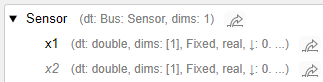
To inspect the attribute values for an element programmatically, use the get_param function.
get_param("BusElementPortCreation/Sensor.x2","OutMin")
ans =
'0.01'
Specify Bus Elements and Their Attributes
When a bus is not defined by a Simulink.Bus object, specify bus elements at the interface with or without adding blocks to the block diagram.
To specify element attributes for existing elements at the port, use the set_param function. For the first argument of this function, specify the element using:
The model name for a root port or the subsystem block path for a subsystem port
The port name
The element path within the port
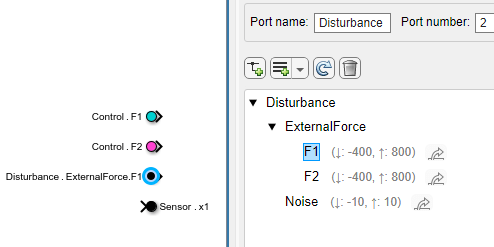
For example, specify attributes of the element named F1 at the Disturbance port. For the first argument, combine the model name (BusElementPortCreation), the port name (Disturbance), and the element path (ExternalForce.F1).
set_param("BusElementPortCreation/Disturbance.ExternalForce.F1", ...
    OutMin="-400", ...
    OutMax="800")
To define a new element at the port, add a block or add the element with the Simulink.Bus.addElementToPort function. To specify the new element, use the first three arguments to provide these values, respectively:
The model name for a root port or the subsystem block path for a subsystem port
The port name
The element path within the port
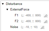
For example, define these additional elements expected at the Disturbance port:
A signal named
NoiseA signal named
F2in the nested bus namedExternalForce
For the first argument, provide the model name (BusElementPortCreation). For the second argument, provide the port name (Disturbance). For the third argument, provide the element path (ExternalForce.F2 or Noise).
Simulink.Bus.addElementToPort("BusElementPortCreation", ...
    "Disturbance","ExternalForce.F2");
Simulink.Bus.addElementToPort("BusElementPortCreation", ...
    "Disturbance","Noise");
After you define a new element at the port, specify the element attributes with the set_param function.
set_param("BusElementPortCreation/Disturbance.ExternalForce.F2", ...
    OutMin="-400", ...
    OutMax="800")
set_param("BusElementPortCreation/Disturbance.Noise", ...
    OutMin="-10", ...
    OutMax="10")
To view the interface definition, double-click the related In Bus Element block or use the Property Inspector.
To inspect the attribute values for an element programmatically, use the get_param function.
get_param("BusElementPortCreation/Disturbance.Noise","OutMin")
ans =
'-10'
Examine Results
This example creates three ports, named Control, Disturbance, and Sensor. While blocks provide access to some of the elements of the ports, other elements are not accessed by blocks. The ports let you specify the attributes of elements regardless of whether blocks access the elements.