Determine Signal Dimensions
Simulink® blocks can output one-dimensional, two-dimensional, or multidimensional signals. The Simulink user interface and documentation generally refer to 1-D signals as vectors and 2-D or multidimensional signals as matrices. A one-element array is frequently referred to as a scalar. A row vector is a 2-D array that has one row. A column vector is a 2-D array that has one column.
A one-dimensional (1-D) signal consists of a series of one-dimensional arrays output at a frequency of one array (vector) per simulation time step.
A two-dimensional (2-D) signal consists of a series of two-dimensional arrays output at a frequency of one 2-D array (matrix) per block sample time.
A multidimensional signal consists of a series of multidimensional (two or more dimensions) arrays output at a frequency of one array per block sample time. You can specify multidimensional arrays with any valid MATLAB® multidimensional expression, such as [4 3]. See Multidimensional Arrays for information on multidimensional arrays.
Simulink blocks vary in the dimensionality of the signals they can accept or output. Some blocks can accept or output signals of any dimension. Some can accept or output only scalar or vector signals.
Note
Simulink does not support dynamic signal dimensions during a simulation. That is, the dimension of a signal must remain constant while a simulation is executing. However, you can change the size of a signal during a simulation. See Variable-Size Signal Basics.
If a block can emit nonscalar signals, the dimensions of the signals that the block outputs depend on the block parameters, if the block is a source block; otherwise, the output dimensions depend on the dimensions of the block input and parameters.
To determine the dimensions that a signal ultimately uses for simulation, first update the block diagram (for example, by pressing Ctrl+D). Then, choose one of these techniques:
Display the dimensions directly on the block diagram. Use this technique to trace signal dimensions along a path of blocks. In the model, on the Debug tab, select Information Overlays > Signal Dimensions).
Inspect the dimensions in the Model Data Editor, which shows you information in a searchable, sortable table. In the table, the right side of each cell in the Dimensions column shows the true dimensions of the corresponding signal line in the model.
Simulink Blocks that Support Multidimensional Signals
The Simulink Block Data Type Support table includes a column identifying the blocks with multi-dimension signal support.
In the MATLAB command line, enter
showblockdatatypetable.A separate window with the Simulink Block Data Type Support table opens.
In the Block column, locate the name of a Simulink block. Columns to the right are data types or features. An X in a column indicates support for that feature.
Simulink supports signals with up to 32 dimensions. Do not use signals with more than 32 dimensions.
Determine the Output Dimensions of Source Blocks
A source block is a block that has no inputs. Examples of source blocks include the Constant block and the Sine Wave block. See Sources for a complete listing of Simulink source blocks. The output dimensions of a source block are the same as those of its output value parameters if the block Interpret vector parameters as 1-D parameter is off (that is, not selected in the block parameter dialog box). If the Interpret vector parameters as 1-D parameter is on, the output dimensions equal the output value parameter dimensions unless the parameter dimensions are N-by-1 or 1-by-N. In the latter case, the block outputs a vector signal of width N.
As an example of how the output value parameters and Interpret vector parameters as 1-D parameter of a source block determine the dimensionality of its output, consider the Constant block. This block outputs a constant signal equal to its Constant value parameter. The following table illustrates how the dimensionality of the Constant value parameter and the setting of the Interpret vector parameters as 1-D parameter determine the dimensionality of the block output.
| Constant Value | Interpret vector parameters as 1-D | Output |
|---|---|---|
scalar | off | one-element array |
scalar | on | one-element array |
1-by-N matrix | off | 1-by-N matrix |
1-by-N matrix | on | N-element vector |
N-by-1 matrix | off | N-by-1 matrix |
N-by-1 matrix | on | N-element vector |
M-by-N matrix | off | M-by-N matrix |
M-by-N matrix | on | M-by-N matrix |
M-by-N-by-1 matrix | off | M-by-N matrix |
M-by-N-by-1 matrix | on | M-by-N matrix |
Simulink source blocks allow you either to specify the dimensions of the signals that they output or specify values from which Simulink infers the dimensions. You can therefore use the source blocks to introduce signals of various dimensions into your model.
Determine the Output Dimensions of Nonsource Blocks
If a block has inputs, the dimensions of its outputs are, after scalar expansion, the same as those of its inputs. For more information, see Signal and Parameter Dimension Rules.
Signal and Parameter Dimension Rules
When creating a Simulink model, you must observe the following rules regarding signal and parameter dimensions.
Block Parameter Dimension Rule
In general, block parameters must have the same dimensions as the dimensions of the inputs to the block. Simulink performs some processing that provides flexibility relating to that general rule.
A block can have scalar parameters corresponding to nonscalar inputs. In this case, Simulink expands a scalar parameter to have the same dimensions as the corresponding input (see Scalar Expansion of Inputs and Parameters).
If an input is a vector, the corresponding parameter can be either an N-by-1 or a 1-by-N matrix. In this case, Simulink applies the N matrix elements to the corresponding elements of the input vector. This exception allows use of MATLAB row or column vectors, which are actually 1-by-N or N-by-1 matrices, respectively, to specify parameters that apply to vector inputs.
Vector or Matrix Input Conversion Rules
Simulink converts vectors to row or column matrices and row or column matrices to vectors under the following circumstances:
If a vector signal is connected to an input that requires a matrix, Simulink converts the vector to a one-row or one-column matrix.
If a one-column or one-row matrix is connected to an input that requires a vector, Simulink converts the matrix to a vector.
If the inputs to a block consist of a mixture of vectors and matrices and the matrix inputs all have one column or one row, Simulink converts the vectors to matrices having one column or one row, respectively.
Note
You can configure Simulink to display a warning or error message if a vector or matrix conversion occurs during a simulation. See Vector/matrix block input conversion for more information.
Scalar Expansion of Inputs and Parameters
Scalar expansion is the conversion of a scalar value into a nonscalar array. Many Simulink blocks support scalar expansion of inputs and parameters. Block-specific descriptions indicate whether Simulink applies scalar expansion to block inputs and parameters.
Scalar expansion of inputs refers to the expansion of scalar inputs to match the dimensions of other nonscalar inputs or nonscalar parameters. When the input to a block is a mix of scalar and nonscalar signals, Simulink expands the scalar inputs into nonscalar signals having the same dimensions as the other nonscalar inputs. For example, a scalar of 4 is expanded to the vector [4 4 4] if the associated nonscalar has a dimension of 3.
Scalar expansion of parameters refers to the expansion of scalar block parameters to match the dimensions of nonscalar inputs.
| Input(s) | Associated Block Parameter | Scalar Expansion |
|---|---|---|
Scalar | Nonscalar | Input expanded to match parameter dimensions. |
Nonscalar | Scalar | Scalar parameter expanded to match number of elements of input. |
Combination of scalar and nonscalar | No corresponding parameter | Scalar inputs expanded to match dimensions of largest nonscalar input. See Scalar and Nonscalar Inputs and No Associated Parameter. |
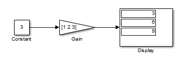
Scalar Input and Nonscalar Parameter
In this example, the Constant block input to the Gain block is scalar. The Gain parameter is a nonscalar value. Simulink expands the scalar input to match the dimensions of a nonscalar Gain parameter, as reflected in the simulation results in the Display block.
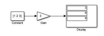
Nonscalar Input and Scalar Parameter
In this example, the Constant block input to the Gain block is nonscalar. The Gain parameter is a scalar value. Simulink expands the scalar parameter to match the dimensions of a nonscalar input from the Constant block, as reflected in the simulation results in the Display block.
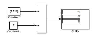
Scalar and Nonscalar Inputs and No Associated Parameter
In this example, the Constant1 block input to the
Sum block is nonscalar, and the
Constant2 block input is scalar. The
Sum block has no associated parameter.
Simulink expands the scalar input from
Constant2 to match to the dimensions of the
nonscalar Constant1 block input. The input is
expanded to the vector [3 3 3].
Get Compiled Port Dimensions
These examples show how to use the CompiledPortDimensions parameter to obtain dimensions of port signals of blocks in a Simulink model during compilation. For nonbus signals, dimensions of port signals represent dimensions of signals associated with the querying port. For buses, dimensions of port signals consist of the type of bus associated with the querying port, the number of signals carried by the bus, and the dimensions of those signals. To display signal dimensions, in the Simulink Editor, on the Debug tab, click Information Overlays > Signals >Signal Dimensions. For more information on signal dimensions, see Signal Dimensions.
Get Compiled Port Dimensions for Nonbus Signal
Get the dimensions of port signals of a Constant block when querying the output port of the Constant block. As the block outputs a nonbus signal, OutSig, the dimensions of the port signals represented by the dim array are the dimensions of the nonbus output signal.
Step through the ex_nonBusPortDim model programmatically using SimulationCommand.
open_system('ex_nonBusPortDim.slx')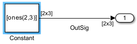
set_param('ex_nonBusPortDim','SimulationCommand','start')
set_param('ex_nonBusPortDim','SimulationCommand','pause')
Store the block name in a variable programmatically using the PortHandles parameter. Then, use the CompiledPortDimensions parameter to obtain the dimensions.
gcb ='ex_nonBusPortDim/Constant';
ph = get_param(gcb,'PortHandles');
dim = get_param(ph.Outport,'CompiledPortDimensions')
dim = 1×3

     2     2     3
For nonbus signals, the result is an array where the first element is 2, which is the number of dimensions of OutSig. The next two elements are 2 and 3, which are the values of dimensions.
To stop the simulation programmatically, use SimulationCommand.
set_param('ex_nonBusPortDim','SimulationCommand','stop')
Get Compiled Port Dimensions for Bus Signals
The following sections show how you can determine signal dimensions at the output port of a Bus Creator block (Bus Creator1) that receives bus signals (both virtual and nonvirtual) at its input ports.
Virtual Bus at Bus Creator block Input and Output ports
In ex_virtualBusPortDim model, Bus Creator1 block receives a virtual bus (NestedBus) at one of its input ports and outputs a virtual bus (TopBus). The dimensions of the port signals represented by the dim array consist of the type of bus associated with the output port of Bus Creator1 block, the number of signals carried by the bus, and the dimensions of those signals.
Step through the ex_virtualBusPortDim model programmatically using SimulationCommand.
open_system('ex_virtualBusPortDim.slx')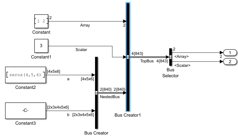
set_param('ex_virtualBusPortDim','SimulationCommand','start')
set_param('ex_virtualBusPortDim','SimulationCommand','pause')
Store the block name in a variable programmatically using the PortHandles parameter. Then, use the CompiledPortDimensions parameter to obtain the dimensions.
gcb ='ex_virtualBusPortDim/Bus Creator1';
ph = get_param(gcb,'PortHandles');
dim = get_param(ph.Outport,'CompiledPortDimensions')
dim = 1×16

    -2     4     1     2     1     1     3     4     5     6     5     2     3     4     5     6
For buses, the results include extra elements. The first element is -2, which indicates that the Bus Creator1 block outputs a virtual bus. The second element is 4, which indicates number of leaf nodes. Signals at these nodes act as input signals of Bus Creator1 block. The subsequent elements follow the same pattern as nonbus signals.
The first leaf node corresponds to the output port of
Constantblock. The signal at the node has one dimension (indicated by1), and the value in that dimension is2.The second leaf node corresponds to the output port of
Constant1block. The signal at the node has one dimension (indicated by1), and the value in that dimension is1.The third leaf node corresponds to the output port of
Constant2block. The signal at the node has three dimensions (indicated by3), and the values in those dimensions are4 5 6.The fourth leaf node corresponds to the output port of
Constant3block. The signal at the node has five dimensions (indicated by5), and the values in those dimensions are2 3 4 5 6.
To stop the simulation programmatically, use SimulationCommand.
set_param('ex_virtualBusPortDim','SimulationCommand','stop')
Nonvirtual Bus at Bus Creator block Input Port and Virtual Bus at Bus Creator block Output Port
In ex_BusPortDim model, Bus Creator1 block receives a non-virtual bus (NestedBus) at one of its input ports and outputs a virtual bus (TopBus).
Step through the ex_BusPortDim model programmatically using SimulationCommand.
open_system('ex_BusPortDim.slx')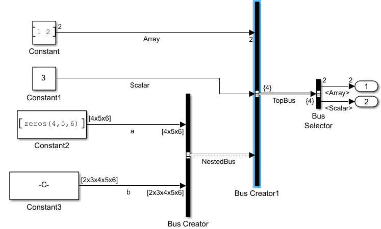
set_param('ex_BusPortDim','SimulationCommand','start')
set_param('ex_BusPortDim','SimulationCommand','pause')
Store the block name in a variable programmatically using the PortHandles parameter. Then, use the CompiledPortDimensions parameter to obtain the dimensions.
gcb ='ex_BusPortDim/Bus Creator1';
ph = get_param(gcb,'PortHandles');
dim = get_param(ph.Outport,'CompiledPortDimensions')
dim = 1×8

    -2     3     1     2     1     1     1     1
When querying dimensions, nonvirtual buses are treated as scalars. The first element is -2, which indicates that the output port of Bus Creator1 block corresponds to a virtual bus. The second element in the dim array is 3, which indicates three leaf nodes instead of four leaf nodes because the nonvirtual bus is treated as scalar. The subsequent elements follow the same pattern as nonbus signals.
The first leaf node corresponds to the output port of
Constantblock. The signal at the node has one dimension (indicated by1), and the value in that dimension is2.The second leaf node corresponds to the output port of
Constant1block. The signal at the node has one dimension (indicated by1), and the value in that dimension is1.The third leaf node corresponds to the Bus Creator block that outputs the nonvirtual bus,
NestedBus. The signal at the node has one dimension (indicated by1), and the value in that dimension is1.
To stop the simulation programmatically, use SimulationCommand.
set_param('ex_BusPortDim','SimulationCommand','stop')
Nonvirtual Bus at Bus Creator block Input and Output ports
In the ex_nonvirtualBusPortDim model, Bus Creator1 block receives a nonvirtual bus (NestedBus) at one of its input ports and outputs a nonvirtual bus (TopBus).
Step through the ex_nonvirtualBusPortDim using SimulationCommand.
open_system('ex_nonvirtualBusPortDim.slx')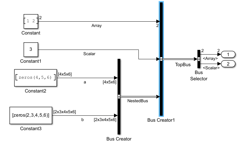
set_param('ex_nonvirtualBusPortDim','SimulationCommand','start')
set_param('ex_nonvirtualBusPortDim','SimulationCommand','pause')
Store the block name in a variable programmatically using the PortHandles parameter. Then, use the CompiledPortDimensions parameter to obtain the dimensions.
gcb ='ex_nonvirtualBusPortDim/Bus Creator1';
ph = get_param(gcb,'PortHandles');
dim = get_param(ph.Outport,'CompiledPortDimensions')
dim = 1×2

     1     1
The output shows 1 element with a dimension of 1 since nonvirtual buses are treated as scalar when querying dimensions.
To stop the simulation programmatically, use SimulationCommand.
set_param('ex_nonvirtualBusPortDim','SimulationCommand','stop')