Isolating Dependencies of an Actuator Subsystem
This example demonstrates highlighting model items that a subsystem depends on. It also demonstrates generating a standalone model slice from the model highlight.
Choose Starting Points and Direction
Open the
f14example model.openExample('simulink/AddBlockFromAnotherModelExample,'f14')On the Apps tab, under Model Verification, Validation, and Test gallery, click Model Slicer.

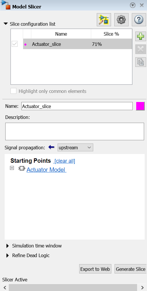
In the Model Slicer, click the arrow to expand the Slice configuration list list. Set the slice properties:
Name:
Actuator_sliceTo the right of Name, click the colored square to set the highlight color. Choose magenta
 from the palette.
Signal Propagation:
upstream.
Add the
Actuator Modelsubsystem as a starting point. In the model, right-click theActuator Modelsubsystem, and in the Model Slicer app section , select Add as Starting Point button
  .
.
View Precedents and Generate Model Slice
The model highlights the upstream dependencies of the
Actuator Modelsubsystem.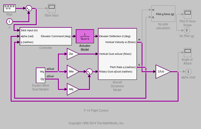
Trace the following dependency path.
Aircraft Dynamics
                            Model
is highlighted via thePitch Rate qsignal, which is an input toController, the output of which feedsActuator Model.Generate a standalone model containing the highlighted model items:
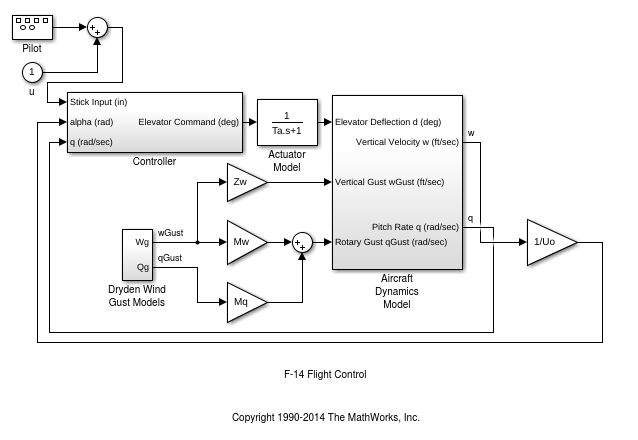
In the Model Slicer, click Generate slice.
In the Select File to Write dialog box, select the save location and enter
actuator_slice_model.Click Save.
The sliced model contains the highlighted model items.
To remove highlighting from the model, close the Model Slicer.