Memory Mapper
Configure memory map for SoC application
Description
View and edit memory regions of an SoC application. Edit device base addresses and offsets for memory-mapped devices.
Using the Memory Mapper tool, you can:
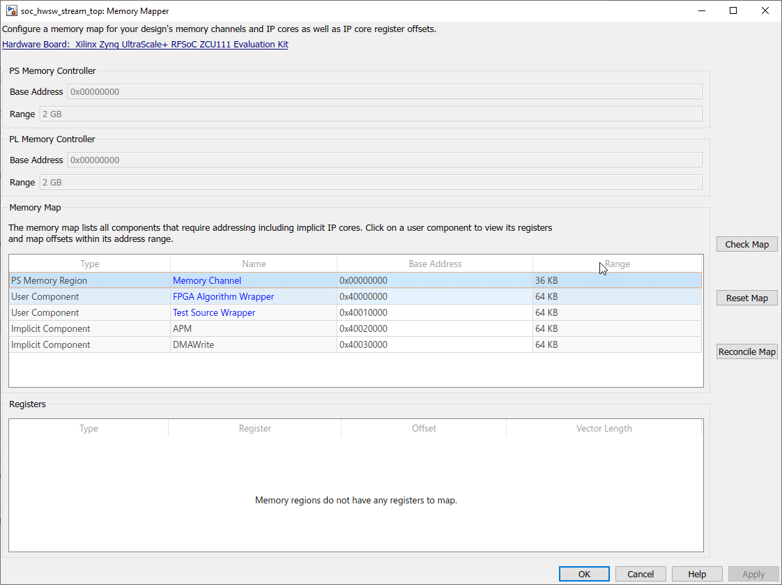
View and edit base addresses, offsets, and memory locations of various channels and memory-mapped components in your design.
Check the memory map of your model for any conflicts between different memory channel configurations.
Reset the memory map to its default settings.
Reconcile an edited map to match model settings.
Open the Memory Mapper
In the Configuration Parameters dialog box, select Hardware Implementation from the left pane. Under Target hardware resources, select FPGA design (top-level) and click View/Edit Memory Map.
In the SoC Builder tool, in the Review Memory Map section, click View/Edit.
Examples
Reconcile Model with Memory Map
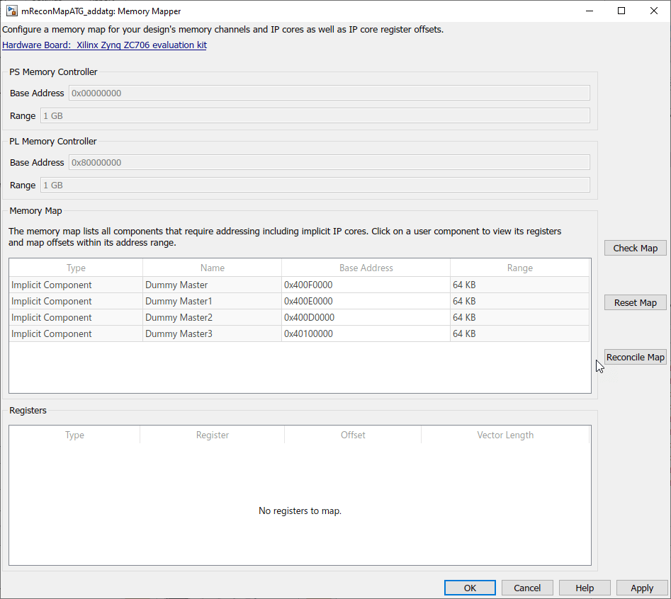
Consider a model with three masters (represented by Memory Traffic Generator blocks), connected to a Memory Controller block.
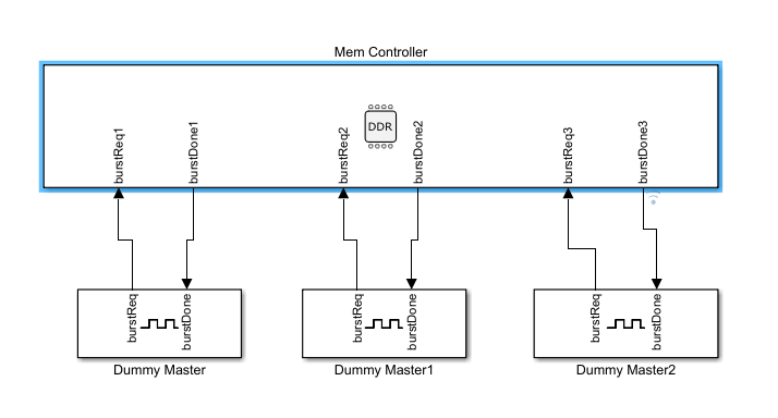
To open the Memory Mapper tool, first open the Configuration Parameters dialog box, and then select Hardware Implementation from the left pane. Under Target hardware resources, select FPGA design (top-level) and click View/Edit Memory Map.
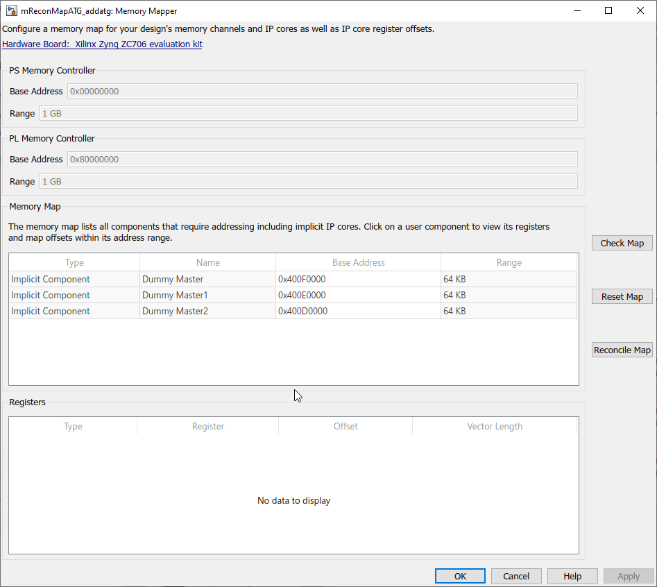
The Memory Mapper lists the three masters in the design. Edit their base addresses as per your requirements. Add another channel to your model.
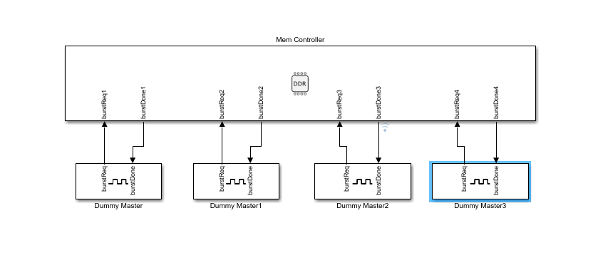
The model consists of four memory channels, while the Memory Map section shows only three. To resolve this conflict, click Reconcile Map. This adds another line, which represents the added channel, to the memory map table.
Reset Map
Click Reset Map to create a new, autogenerated map. The base addresses of the channels are reset to a default value.

Related Examples
Parameters
Version History
Introduced in R2019a
See Also
You can also select a web site from the following list:
Americas
- América Latina (Español)
- Canada (English)
- United States (English)
Europe
- Belgium (English)
- Denmark (English)
- Deutschland (Deutsch)
- España (Español)
- Finland (English)
- France (Français)
- Ireland (English)
- Italia (Italiano)
- Luxembourg (English)
- Netherlands (English)
- Norway (English)
- Österreich (Deutsch)
- Portugal (English)
- Sweden (English)
- Switzerland
- United Kingdom (English)