Compound Motor
Compound motor model with electrical and torque characteristics and fault modeling
Libraries:
Simscape /
Electrical /
Electromechanical /
Brushed Motors
Description
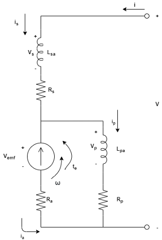
The Compound Motor block represents the electrical and torque characteristics of a compound motor. This figure shows the equivalent circuit for a short-shunt compound motor:
This figure shows the equivalent circuit for a long-shunt compound motor:
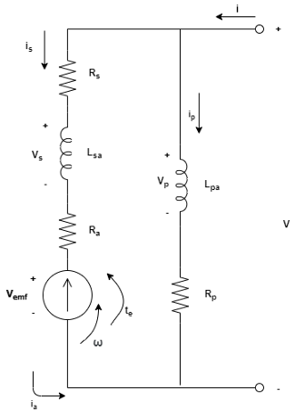
where:
i is the total current.
is is the series field winding current.
ip is the parallel field winding current.
ia is the armature current.
V is the total voltage.
Vs is the series field winding voltage.
Vp is the parallel field winding voltage.
Va is the armature voltage.
ω is the angular velocity.
te is the torque.
If you set the Steady-state parameterization parameter to
By equivalent circuit parameters, you can specify the
equivalent circuit parameters for this model:
Ra — Armature resistance, Ra
Rs — Series field winding resistance, Rs
Rp — Shunt field winding resistance, Rp
Lsa — Series field winding to armature back EMF constant, Lsa
Lpa — Shunt field winding to armature back EMF constant, Lpa
Short-Shunt Equations
When Electrical circuit topology is set to
Short-shunt, the electrical dynamic equations
are:
These are the mechanical dynamic equations for the short-shunt compound motor:
From these dynamic equations, the block obtains the steady-state equations by making the derivatives equal to zero:
Then, it computes the steady-state currents and torque as follows:
Long-Shunt Equations
When Electrical circuit topology is set to
Long-shunt, the electrical dynamic equations
are:
These are the mechanical dynamic equations for the long-shunt compound motor:
From these dynamic equations, the block obtains the steady-state equations by making the derivatives equal to zero:
Then, it computes the steady-state currents and torque as follows:
Faults
To model a fault in the Compound Motor block, in the Faults section, click Add fault next to the fault that you want to model. For more information about fault modeling, see Fault Behavior Modeling and Fault Triggering.
The Compound Motor block allows you to model three types of faults:
Armature winding fault — The armature winding fails and becomes open circuit.
Series field winding fault — The series field winding fails and becomes open circuit.
Shunt field winding fault — The shunt field winding fails and becomes open circuit.
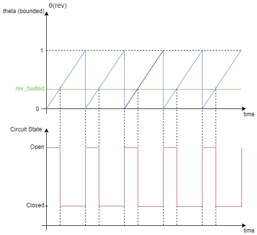
When the armature fails, the voltage source connected to this block observes an open
circuit for a fraction of the total motor revolution, specified by the
Fraction of revolution during which armature is
open-circuit parameter. This figure illustrates the circuit state
behavior and the open-circuit state (rev_faulted) for a
revolution period:
You specify how and when faults occur by using the Trigger type parameter.
If you set the Trigger type to Behavioral,
the Compound Motor block triggers faults when the winding currents continuously
exceed a threshold value for longer than a specific time interval:
Armature winding faults occur when the winding currents continuously exceed the value of the Maximum permissible armature winding current parameter for a duration longer than the value of the Time to fail when exceeding armature winding current parameter.
Series field winding faults occur when the winding currents exceed the value of the Maximum permissible series field winding current parameter for a duration longer than the value of the Time to fail when exceeding series field winding current parameter.
Shunt field winding faults occur when the winding currents exceed the value of the Maximum permissible shunt field winding current parameter for a duration longer than the value of the Time to fail when exceeding shunt field winding current parameter.
If you set the Trigger
type to Conditional, you can choose whether faults
in the Compound Motor block are reversible (since R2025a). To model irreversible faults, click
Open fault properties to open the Property Inspector and select the
Trigger stays on once activated parameter. The block enters the faulted
state when the trigger condition becomes true for the first time and remains in the faulted
state for the rest of the simulation. To model reversible faults, clear the Trigger
stays on once activated parameter. The block enters the faulted state when the
trigger condition is true and enters the unfaulted state when the trigger condition is
false.
For more information about adding faults to blocks and specifying fault triggers, see Introduction to Simscape Faults.
Model Thermal Effects
You can expose thermal ports to model the effects of losses that convert power to heat. To expose the thermal ports, set the Modeling option parameter to either:
No thermal port— The block does not contain thermal ports.Show thermal port— The block contains thermal conserving ports for the series field winding, the shunt field winding, and the armature.
For more information about using thermal ports in actuator blocks, see Simulating Thermal Effects in Rotational and Translational Actuators.
Examples
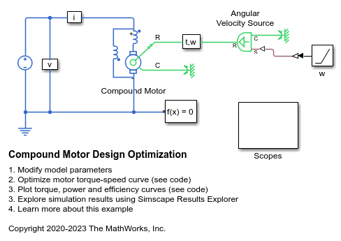
Compound Motor Design Optimization
Find design parameters that optimize a compound motor torque-speed curve to match the desired curve.
Ports
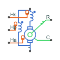
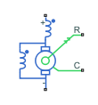
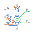
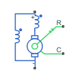
The type, visibility, and location of the block ports depend on how you configure the Electrical circuit topology parameter in the Configuration tab, and if you expose the thermal ports:
| Electrical circuit topology | Thermal ports | Block |
|---|---|---|
Long-shunt | Hidden |
|
Visible |
| |
Short-shunt | Hidden |
|
Visible |
|