BMS Cell Voltage Monitoring and SOC Estimation on C2000 Microcontroller
R2026bThis example shows how to monitor cell voltages and estimate state of charge (SOC) for a lithium-ion battery pack using a C2000™ microcontroller and a BQ79718 analog front end. You simulate and validate the estimation algorithms in Simulink®, then generate and deploy C code to a Texas Instruments® (TI) LAUNCHXL-F28P55X LaunchPad using C2000 Microcontroller Blockset. The BQ79718B-Q1 analog front end (AFE) acquires cell voltages and communicates with the LaunchPad over UART.
This example supports two configurations:
Single device (18S) — One BQ79718EVM monitors an 18-cell pack.
Daisy chain (36S) — Two BQ79718EVMs in a daisy chain monitor a 36-cell pack.
Required Hardware
Single Device (18S)
Component | Description |
|---|---|
TI LAUNCHXL-F28P55X LaunchPad | Microcontroller (MCU) development board (F28P55x series) |
BQ79718EVM | Evaluation module for the BQ79718B-Q1 AFE |
DC voltage source (75 V, 1 A minimum) | Simulates the 18-cell lithium-ion battery stack input |
Note: The BQ79718EVM is not commercially available. Use a custom board that meets the BQ79718/BQ79758 interface requirements.
Daisy Chain (36S)
In addition to the single-device hardware, daisy-chain operation requires one additional EVM:
BQ79718EVM #1 — base device connected to the MCU; measures cell voltages for cells 1–18.
BQ79718EVM #2 — stack device daisy-chained to the base device; measures cell voltages for cells 19–36.
Open MATLAB Project
This MATLAB® project contains all example models, data scripts, and custom C files. To open the project, click the Open Project hyperlink below or run the following command:
openExample("c2b/DeployBMSCellMonitorToC2000Example")Available Models
The target models generate code for the C2000 MCU. The host models run on the host computer to display live cell voltages and SOC from the deployed target.
Target Models
Model | Configuration | Description |
| 18S (1 device) | Single BQ79718 cell monitor |
| 36S (2 devices) | Daisy-chain with auto-addressing |
Host Models
Model | Configuration | Description |
| 18S | Receives 18 cell voltages + SOC via serial |
| 36S | Receives 36 cell voltages + SOC via serial |
All models share the parameter script c2000BMSData.m. Each model sets numberOfDevices in its InitFcn callback before calling the data script.
Data Flow: AFE to Host ECU
c2000BMSSingleDeviceModel implements a cell voltage monitoring and SOC estimation pipeline. The C2000 MCU communicates with the AFE over a 1 Mbps UART connection, reads 18 cell voltages, estimates SOC, and reports results to a host electronic control unit (ECU) over UART and CAN.
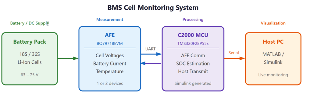
Pipeline Subsystems
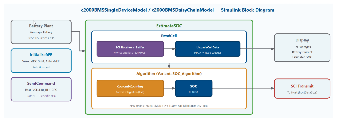
Both models implement the same pipeline:
InitializeAFE — Sends wake pulse, auto-addressing, and ADC start commands to the BQ79718 device(s) over SCIB UART at 1 Mbps.
SendCommand — Constructs a single-read request for cell voltage registers and transmits it periodically.
SCI Receive with Buffer — Accumulates FIFO interrupts into a complete response frame using the MW_dataBuffer.c ring buffer.
ReadCellVoltages — Unpacks HI/LO byte pairs into cell voltages.
EstimateSOC — Estimates SOC using Coulomb counting (current integration).
The daisy-chain model extends this with a two-device initialization sequence (directed writes for auto-addressing, TOP_STACK configuration) and a doubled buffer size (100 bytes) to accommodate responses from both devices. For a detailed breakdown of each stage, see Cell Voltage Monitoring Pipeline.
Model Simulation
To verify algorithm behavior before deploying to hardware, simulate the model with a Simscape Battery plant model. The Simscape Battery block models an 18S (or 36S) series-connected lithium-ion pack with realistic voltage and SOC dynamics. To run the simulation, on the Simulation tab, click Run.
The model InitFcn callback runs c2000BMSData.m automatically to load workspace variables. This script defines register addresses, frame sizes, and battery parameters:
% numberOfDevices = 1;
% run("c2000BMSData.m")  % Single device (18S). Ensure "c2000BMSData.m" is in the current folder or on the MATLAB path

% numberOfDevices = 2;
% run("c2000BMSData.m")  % Daisy chain (36S)
Simulation Results
Visualize the cell voltages on the display blocks in the Simulink canvas.
Each value is the terminal voltage of one cell in the Simscape™ Battery™ pack. The pack voltage equals the sum of all 18 or 36 cells. Per-cell values in the 3.5–4.2 V range confirm that the model correctly senses voltages across the full SOC range.
The EstimateSOC subsystem operates at a 1-second update period. The initial SOC estimate is 0.5 (50%), and the algorithm bounds the output to the range [0.0, 1.0].
The SOC estimate tracks the battery state as the Simscape Battery model charges and discharges. The Coulomb counting method integrates current over time to track charge consumed or added to the pack.
This example uses Coulomb counting with OCV correction. For a more advanced estimator, such as an extended Kalman filter, see the Battery State-of-Charge Estimation example (Simscape Battery). To compare different estimation techniques, see Explore Techniques to Estimate Battery State of Charge.
SOC Estimation Method
The EstimateSOC subsystem uses a variant selection (SOC_Algorithm in c2000BMSData.m) to choose between two estimation techniques. Only one is active at a time.
Coulomb Counting (
SOC_Algorithm= 1, default) — Integrates current over time to track charge flow. Uses the SOC Estimator (Coulomb Counting) block from the Simscape Battery library. Requires a current measurement (Ibat).Voltage Lookup Table (
SOC_Algorithm= 2) — Maps pack voltage to SOC through a discharge curve (OCV table) defined inc2000BMSData.m. For example, a cell at 3.65 V corresponds to approximately 50% SOC. Does not require a current measurement but is accurate only at rest (open-circuit conditions).
Note: The BQ79718B-Q1 does not have an integrated current sense amplifier (CURRENT registers read 0). To use Coulomb counting on hardware, connect an external current sensor. Without one, use the voltage lookup table variant. The BQ79758-Q1 (an AFE with integrated current sensing) is an alternative that supports Coulomb counting without an external sensor.
Connect Hardware
Single Device (18S)
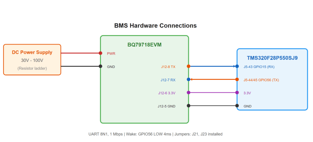
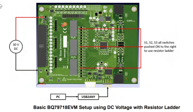
To prepare the hardware for deployment, connect the BQ79718EVM to the LaunchPad and apply power. Connect the DC voltage source to the EVM BATT+ and BATT− terminals to simulate the battery stack.
Daisy Chain (36S)
For daisy-chain operation, connect two BQ79718EVMs. The MCU communicates with the base EVM (dev0), which relays commands to the stack EVM (dev1) via the COMH-to-COML link.
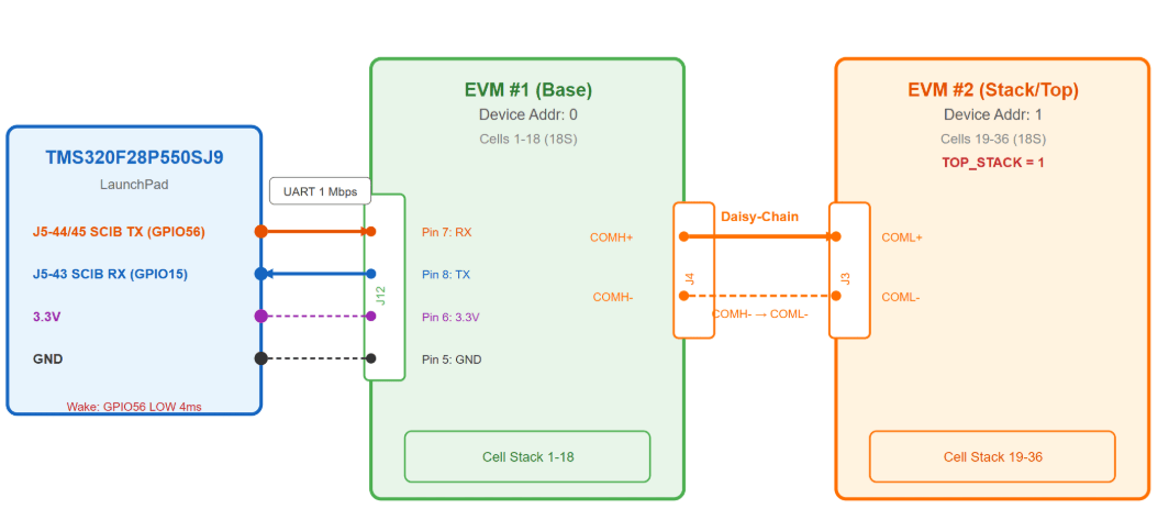
MCU to Base EVM (dev0)
MCU Pin | EVM Pin | Signal |
J5-44/45 (GPIO56) | J12 Pin 7 | MCU TX → EVM RX |
J5-43 (GPIO15) | J12 Pin 8 | EVM TX → MCU RX |
GND | J12 GND | Common ground |
Daisy-Chain Link (Base to Stack)
Base EVM Pin | Stack EVM Pin | Signal |
J4 COMH TX | J3 COML RX | Data uplink |
J4 COMH RX | J3 COML TX | Data downlink |
Base EVM (dev0) Jumper Settings
Jumper | Setting |
J7, J8, J9 | Installed (UART isolator) |
J10 | Installed (COMH enabled for daisy chain) |
J21, J23, S1-S3 | Installed |
Stack EVM (dev1) Jumper Settings
Jumper | Setting |
J7, J8, J9 | Removed (no MCU connection) |
J10 | Removed (topmost device) |
J21, J23, S1-S3 | Installed |
For EVM jumper settings, contact TI for EVM user guide. For LaunchPad header pin outs, see the LAUNCHXL-F28P55x Quick Start Guide on the TI website.
Cell Voltage Monitoring Pipeline
The model implements a six-step data pipeline that periodically reads cell voltages from the AFE (18 per device):
Step | Component | Action |
1 | SendCommand | Constructs a single-read request to |
2 | SCIB RX ISR | SCIB interrupt fires after 5 bytes arrive (FIFO interrupt level = 5) |
3 |
| Accumulates 5-byte chunks into a 50-byte (18S) or 100-byte (36S) ring buffer; returns data-ready flag when full |
4 | SCI Receive with Buffer | Detects data-ready flag and passes the complete frame to downstream processing |
5 | ReadCellVoltages | Unpacks data bytes into |
6 | EstimateSOC | Estimates SOC using OCV correction and Coulomb counting |
Each BQ797x device replies to a Single-Device Read with a fixed 50-byte frame. The trailing padding byte keeps the frame size a multiple of the SCI FIFO interrupt level (5 bytes), so RX interrupts always fire on whole-frame boundaries.
Offset | Bytes | Field |
1 | 1 | Init |
2 | 1 | Device address |
3–4 | 2 | Register address (HI, LO) |
5–40 | 36 | VCELL data (18 cells × 2 bytes) |
41–42 | 2 | Vcell_actual_sum |
43–44 | 2 | VBAT |
45–47 | 3 | CURRENT (24-bit signed) |
48–49 | 2 | CRC-16 |
50 | 1 | Padding |
For a single device (18S), the receive buffer is 50 bytes — one frame.
For the daisy-chain configuration (36S, two devices), the buffer is 100 bytes: device 0's frame occupies bytes 1–50 and device 1's frame occupies bytes 51–100. The ring buffer notifies the model when the first 50 bytes arrive so it can trigger the second device's read; the full 100 bytes then complete the response and are handed to the decoder.
Single Device Initialization Sequence
Step | Command | Description |
1 | GPIO56 wake pulse | 4 ms LOW pulse to wake the base device from SHUTDOWN |
2 | ADC_CTRL2 | Start continuous ADC conversion ( |
Daisy-Chain Initialization Sequence
c2000BMSDaisyChainModel uses a multi-step initialization for two devices:
Step | Command | Description |
1 | GPIO56 wake pulse | 4 ms LOW pulse to wake the base device from SHUTDOWN |
2 | SEND_WAKE (dev0) | Dev0 forwards wake to dev1 via COMH daisy-chain link |
3 | CONTROL1 (directed write) | Enable daisy-chain communication on all devices |
4 | DIR0_ADDR (directed write) | Auto-address: assign address 0 to base, 1 to stack |
5 | TOP_STACK (dev1) | Mark dev1 as the topmost device in the chain |
6 | ACTIVE_CELL (both) | Configure 18S mode on both devices |
7 | ADC_CTRL2 (both) | Start continuous ADC conversion ( |
The MCU connects only to the base device (dev0). The stack device (dev1) is reached through the COMH-to-COML daisy-chain link. The J10 jumper on the base EVM must be installed to enable the COMH uplink.
Communication Protocol
The BQ79718B-Q1 uses a proprietary UART protocol at 1 Mbps:
CRC-16-IBM — Polynomial
0x8005, init0xFFFF, reflected I/O. Implemented ingenerateChecksum.m(MATLAB) and in C init code.Single Read (
0x80) — Requests N registers starting from a specified address.Single Write (
0x90) — Writes one register on a specified device.Directed Write (
0xD0) — Broadcasts a write for auto-addressing (daisy chain).Response frame format (per device):
[InitByte][DevAddr][RegAddr_HI][RegAddr_LO][Data...][CRC_LO][CRC_HI]
1 byte 1 byte 1 byte 1 byte N bytes 1 byte 1 byte
Custom C Code Integration
The model integrates custom C code, provided with this example, for UART data buffering:
MW_dataBuffer.candMW_dataBuffer.h— Ring buffer that accumulates SCI FIFO data into complete response frames. Supports both single-device (50 bytes) and daisy-chain (100 bytes) modes.generateChecksum.m— CRC-16-IBM reference implementation for validating UART frames in MATLAB.
These files reside in the components/ folder. The model includes them via the CustomSource and CustomHeaderCode parameters.
Generate and Deploy Code to Target Hardware
Simulink generates C code from the model and deploys it to the LaunchPad over USB.
To confirm algorithm behavior before deploying, simulate the target model (
c2000BMSSingleDeviceModelorc2000BMSDaisyChainModel). If you have not already done so, on the Simulation tab, click Run.To prepare for deployment, complete hardware connections between the LaunchPad and the BQ79718EVM as described in Connect Hardware.
To configure for your hardware, open the target model. If your hardware uses a different SCIB channel or baud rate, on the Modeling tab, click Model Settings. In the Configuration Parameters dialog box, navigate to Hardware Implementation > Target hardware resources > SCI_B, and update the Baud rate parameter. The default is 1000000 (1 Mbps).
To generate code and deploy to the LaunchPad, on the Hardware tab, click Build, Deploy & Start.
Verify Deployment on Hardware
To open the host model, click the hyperlink in the target model or run one of the following commands:
% open_system("c2000BMSSingleDeviceHostModel")  %18S
% open_system("c2000BMSDaisyChainHostModel")    %36S
To connect to the target hardware, set the COM port parameter in the host model Serial Receive and Serial Transmit blocks to match the port assigned to your LaunchPad. To find the COM port, open Windows Device Manager and look under Ports (COM & LPT) for the entry labeled "XDS110 Class Application/User UART."
To start receiving data from the target, on the Simulation tab, click Run.
Verify that cell voltages appear in the 3.5–4.2 V range per cell in the Display blocks. SOC estimates update at 1-second intervals. If values show 0 or NaN, check UART wiring and baud rate settings.
Next Steps
After you deploy the BMS cell monitor, you can:
Add an external current sensor to enable Coulomb counting alongside the OCV lookup, improving SOC accuracy under dynamic load.
Implement an extended Kalman filter for SOC estimation to reduce drift during sustained charge-discharge cycles.
Add cell balancing logic to equalize voltages across the pack, extending pack life by preventing individual cells from reaching cutoff limits.
Extend the CAN interface to report cell-level diagnostics to a vehicle network for fleet-level monitoring.
See Also
Related Examples
Concepts
Copyright © 2026 The MathWorks, Inc.

