Configure CLB Peripheral for TI C2000 Processors
R2026bThe Configurable Logic Block (CLB) peripheral on Texas Instruments® C2000™ processors enables you to build custom digital logic systems without an external FPGA. You can use CLB to implement state machines, combinatorial logic, and signal conditioning by configuring digital inputs, outputs, and logic equations across up to six CLB tiles.
The C2000 Microcontroller
Blockset provides a configuration interface in the model configuration
parameters to set up CLB tile inputs, outputs, and routing. You define the digital logic
using the SysCfg tool in Code Composer Studio (CCS) v20 or later. The tool generates the
clb_config.h and clb_config.c files that you
include in your Simulink® model for code
generation.
To configure CLB for your application, address three aspects:
Inputs — What digital signals feed into the CLB logic? Configure through tile input selections (global, local, or GPIO) and CLB XBAR routing.
Outputs — Where do the CLB logic results go? Route tile outputs to peripherals, XBARs, or other CLB tiles.
Logic — What digital logic equations process the inputs? Define using the SysCfg tool, which generates configuration files for code generation.
Choose Input Type for CLB Tiles
Each CLB tile has eight boundary inputs (IN0 through IN7). For each input, you select one of three input types in the model configuration parameters.
Global inputs. Peripheral signals from ePWM, Embedded Real-Time Analysis and Diagnostics (ERAD), SPI, and Fast Serial Interface (FSI) modules, and CLB output signals rerouted from other tiles and AUXSIG0 through AUXSIG7 signals from CLB XBAR. For details on routing peripheral signals through CLB XBAR, see Configure CLB XBAR for TI C2000 Processors.
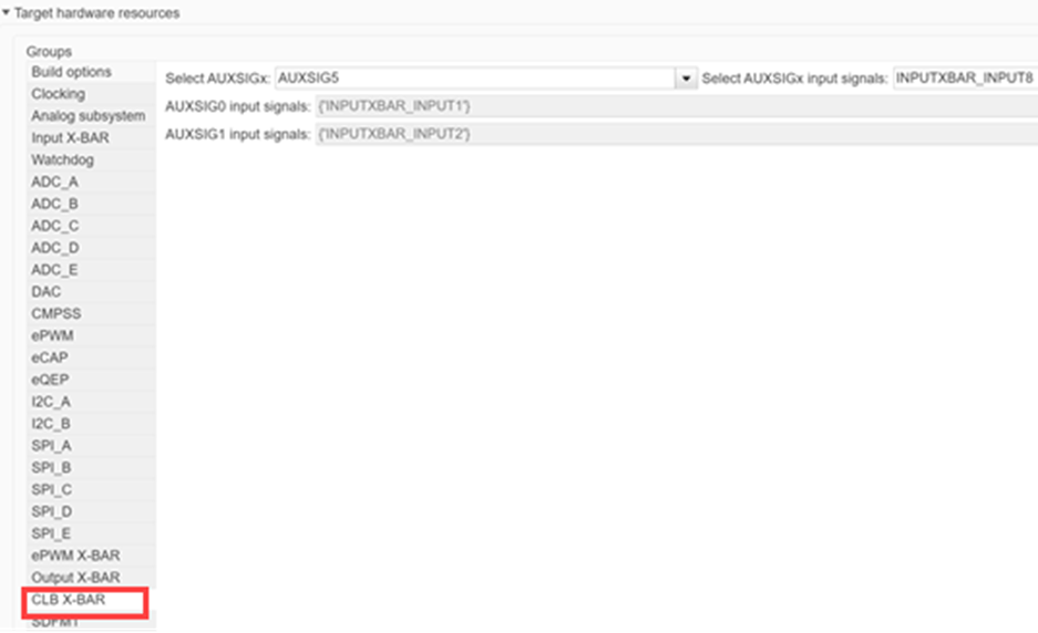
Local inputs. Peripheral signals from ePWM, eCAP, and SPI modules, and CLB INPUT XBAR signals (INPUTXBAR 17 through 32).
General purpose register (GPREG). Static digital values (0 or 1) assigned to each of the eight boundary inputs. Use GPREG inputs when you need fixed logic levels for testing or when a specific input must remain constant during operation.
Note
CLB5 and CLB6 have different available input options compared to CLB1 through CLB4. Verify the available signals for your target tile in the configuration parameters.
Configure CLB Tile Inputs and Outputs
Before you configure CLB tile parameters, design your digital logic in the SysCfg tool so that you know which inputs and outputs your logic requires. The configuration parameters in Simulink must match the logic defined in your SysCfg-generated files.
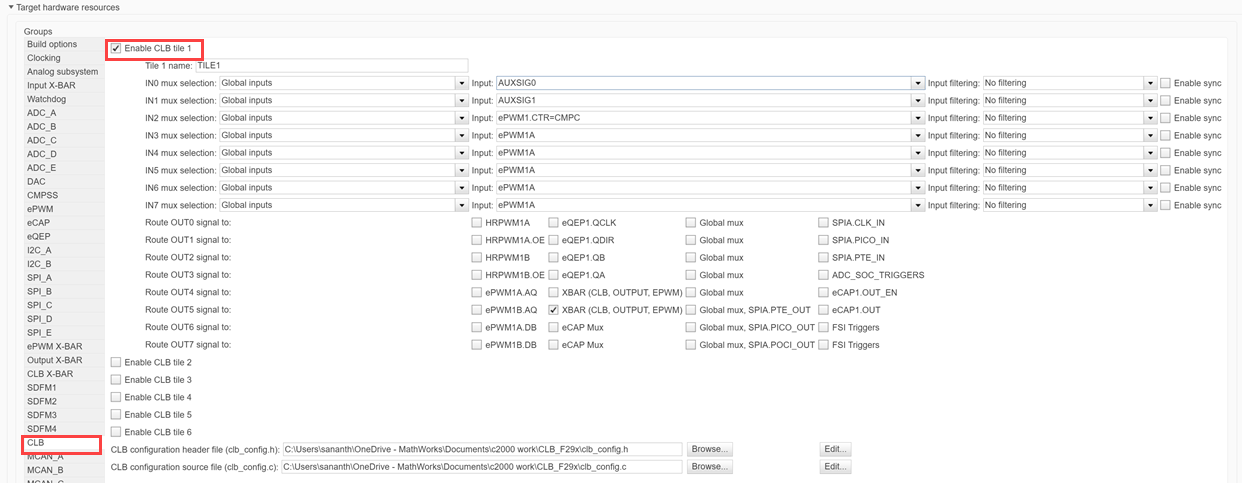
To access CLB settings, in your Simulink model, on the Modeling tab, click Model Settings. In the Configuration Parameters dialog box, click Hardware Implementation and select the CLB tab under Target Hardware Resources.
Enable Tiles and Assign Names
To enable a CLB tile, select the check box for the tile you want to configure.
In the Tile # Name box, specify a name that matches the tile name used in the SysCfg tool.
Note
The tile name in the configuration parameters must exactly match the name in the SysCfg tool. If the names do not match, code generation produces a warning.
Select Input Signals
For each of the eight inputs (IN0 through IN7) on a tile:
In the IN# MUX selection parameter, select the input type: global, local, or GPREG.
In the Input parameter, select the specific signal source based on your chosen input type.
To apply edge filtering, in the Input filtering parameter, select the detection mode: rising edge, falling edge, or any edge.
To synchronize the input signal with the CLB clock domain, select the Enable sync check box.
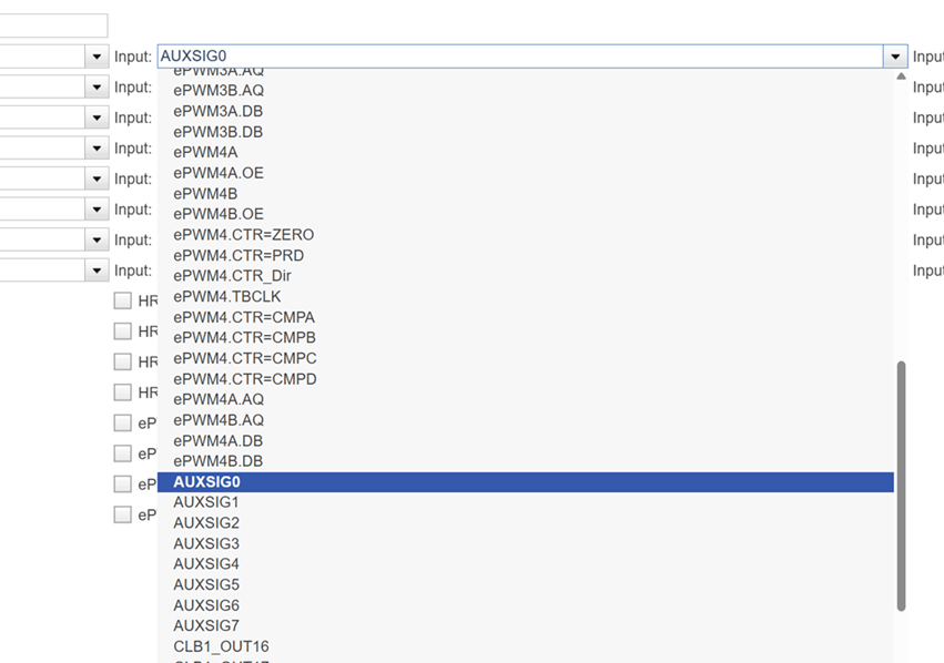
Input filtering and synchronization help produce clean signal transitions at the CLB tile boundary. Enable synchronization if the input signal originates from a clock domain different from the CLB peripheral clock.
Route Output Signals
Each CLB tile produces eight outputs (OUT0 through OUT7) that the device replicates to create 16 output signals. You can route these signals to ePWM, eCAP, eQEP, and crossbar modules on the device.
To configure an output destination, in the Route OUT# signal to parameter, select the target peripheral or crossbar for each output signal. You can also route CLB outputs to OUTPUT XBAR for use by other peripherals or to another CLB tile for cascaded logic operations.
Generate CLB Logic Using SysCfg Tool
The CLB configuration files define the digital logic equations that process your configured inputs. The SysCfg tool in CCS v20 or later provides a graphical interface for defining look-up tables (LUTs), finite state machines (FSMs), counters, and output conditioning logic.
Import CLB Example Project
To set up the SysCfg environment for TI C2000 CLB:
Open CCS v20 or later.
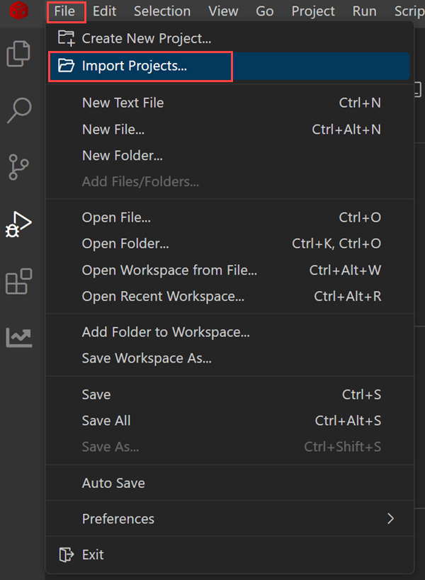
To import the CLB example project, click File > Import Projects.
Click Browse and navigate to the CLB example path in the F29x SDK:
<F29x SDK
                                path>/examples/driverlib/single_core/clb/clb_ex1_combinatorial_logic
Select the processor folder (for example,
f29h85x) and click Finish.
This project includes the SysCfg infrastructure that CLB configuration requires.
Create SysCfg Configuration
To create a new SysCfg file, right-click the imported project folder, then select System Configurations > Create New.
In the board and device selection page, select the appropriate device options and click Confirm.
In the SysCfg editor, in the CONTROL section, click the CLB peripheral.
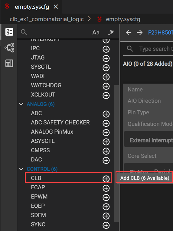
To add a CLB instance, click + next to CLB.
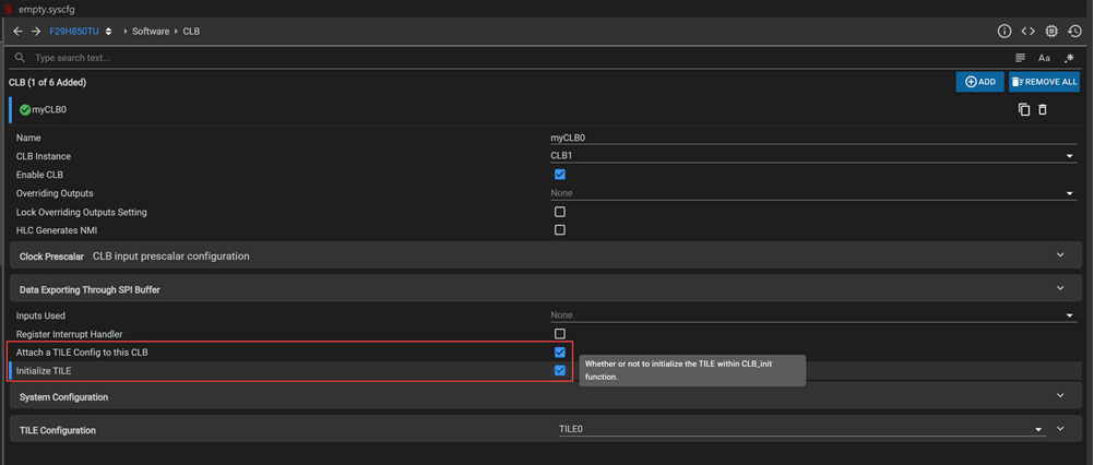
To enable the instance, select the enable check box.
To attach a tile, select the tile check box and select the Initialize TILE check box.
Note
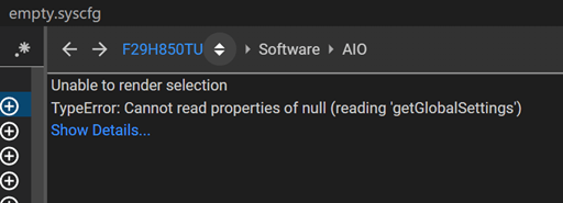
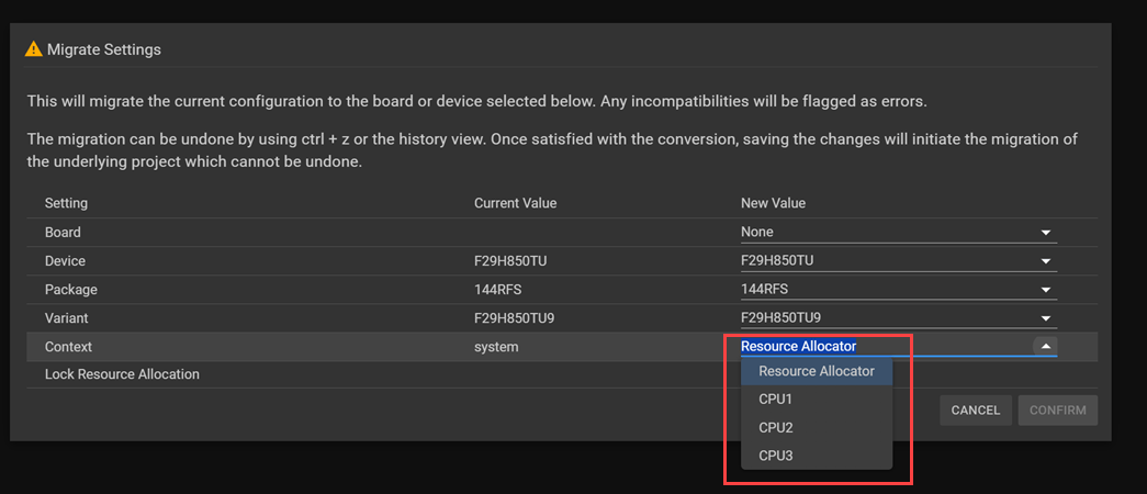
If the CLB section does not render correctly, you have not assigned the CPU to the processor context. To resolve this issue, click the dropdown next to the processor name (for example, F28H850TU). In the Migrate Settings page, click the Context Setting box that shows Resource Allocator, select the appropriate CPU from the dropdown, and click Confirm.
Define Digital Logic
In the TILE Configuration section:
Set the tile name to match the name used in the Simulink configuration parameters.
To configure look-up tables (LUTs), select up to four logic inputs per LUT and specify the logic equation using Boolean operators. For example, the equation
(i0&i1) | (i2^i3)performs AND on inputs 0 and 1, XOR on inputs 2 and 3, then OR combines the results.Configure the FSM, counter, output look-up table, and asynchronous output conditioning block based on your application requirements.
In the output look-up table, specify the output logic equation based on three input fields (
i0,i1,i2).
For more information about CLB logic configuration options, see the Texas Instruments C2000 SDK CLB documentation.
Export Configuration Files
To view generated source code, click Generated Code in the SysCfg editor.
Click the
clb_config.hfile and save it to a location accessible from your Simulink model folder.Click the
clb_config.cfile and save it to the same location.
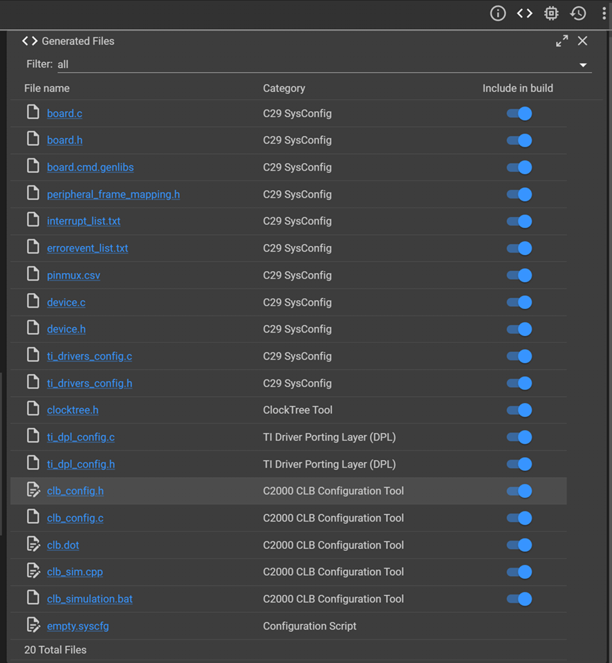
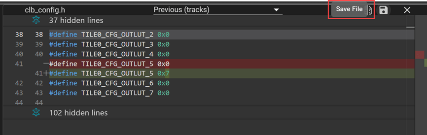
These two files contain the register configurations that define your digital logic. To initialize the CLB tile logic at startup, code generation includes these files in the build process.
Include Configuration Files in Model
After exporting the configuration files from SysCfg, reference them in the model configuration parameters so that code generation includes them in the build:
In the CLB tab of the Configuration Parameters dialog box, in the CLB configuration header file (clb_config.h) box, enter or browse to the path of your header file.
In the CLB configuration source file (clb_config.c) box, enter or browse to the path of your source file.

Note
Verify that the file paths resolve correctly relative to your model location. Incorrect or unresolvable paths produce a warning during code generation.
Build and Verify Model
After configuring tile inputs, outputs, and referencing the SysCfg-generated files, build the model:
To generate deployment code, build the model. During startup, the generated code calls the
configureCLBandconfigureCLBXbarinitialization functions inMW_c28xx_clb.c.To verify CLB output signals on hardware, use a GPIO block or the Register R/W block to observe logic output values at the configured output pins.
You can use external mode to monitor CLB outputs in real time during execution on the target hardware.
Supported Workflows and Deployment Options
CLB configuration supports these deployment workflows:
| Workflow | Description |
|---|---|
| Code generation | Generate standalone C code for deployment to TI C2000 hardware |
| External mode | Monitor and tune parameters on live hardware from Simulink |
| Reference models | Use CLB-configured models as referenced components in larger systems |
| Multicore | Deploy CLB across multiple CPU cores on the TI C2000 device |
Limitations
The blockset does not support writing CLB logic directly in Simulink. You must use the SysCfg tool in CCS to define logic equations and export configuration files.
The blockset currently supports the F29H85x processor. The blockset does not yet support the F28P58x processor.
F29x SysCfg support requires CCS v20 or later.

