R2026b

New Features, Compatibility Considerations

 ArduPilot Autopilots: Read ArduPlane estimator outputs

The UAV Toolbox Support Package for ArduPilot® Autopilots introduces these blocks for reading ArduPlane estimator outputs in Simulink® models:

In addition, these blocks now support ArduPlane:

For an example of how to use these blocks to model a fixed-wing plant in a software-in-the-loop simulation, see the Run ArduPilot Software-in-the-Loop Simulation with Fixed-Wing Plant in Simulink example.
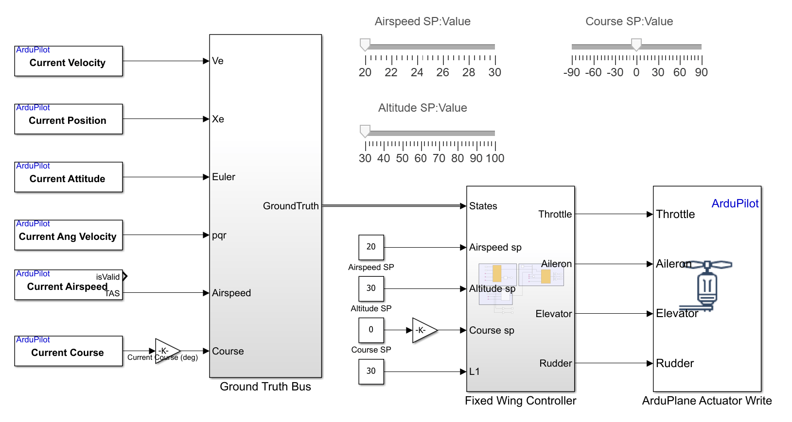
Simulink model showing ArduPlane estimator blocks reading airspeed, course, and attitude, feeding a fixed-wing controller with actuator output.

ArduPilot Autopilots: Read and write parameters

The UAV Toolbox Support Package for ArduPilot Autopilots introduces these blocks for reading parameters from and writing parameters to an ArduPilot autopilot:

  • Read Parameter — Reads parameter values from an ArduPilot autopilot. Use this block when you need to monitor or log configuration parameters, such as PID gains or system settings, during simulation or deployment.

  • Write Parameter — Writes parameter values to an ArduPilot autopilot. Use this block to modify configuration parameters during simulation or execution, such as tuning control gains or updating system settings.
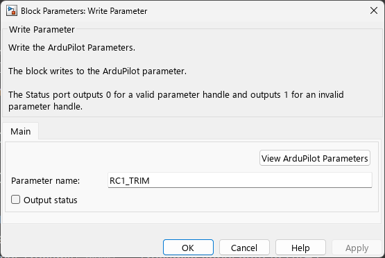
Block Parameters dialog box for the Write Parameter block, showing the Parameter name box and Output status option.

ArduPilot Autopilots: New peripheral blocks

The UAV Toolbox Support Package for ArduPilot Autopilots introduces these blocks for communicating with peripherals connected to an ArduPilot autopilot:

  • I2C Controller Read — Reads data from I2C peripherals connected to an ArduPilot autopilot.

  • I2C Controller Write — Writes data to I2C peripherals connected to an ArduPilot autopilot.

  • Serial Receive — Receives serial data from UART peripherals connected to an ArduPilot autopilot.

  • Serial Transmit — Transmits serial data to UART peripherals connected to an ArduPilot autopilot.

For an example of communicating with peripherals connected to an ArduPilot autopilot over I2C, see the Read Distance Using VL53L4CD ToF Sensor Over I2C with ArduPilot Autopilot example.
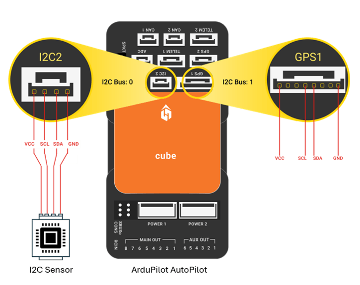
I2C sensor and GPS1 peripheral connected to Pixhawk Cube board through I2C Bus 0 and Bus 1

ArduPilot Autopilots: Log Simulink signals to ArduPilot DataFlash logs

Use the DataFlash Log block to log Simulink signals to ArduPilot DataFlash logs on an SD card used by supported ArduPilot autopilots.

This block enables you to log Simulink signals together with standard ArduPilot flight log data, such as sensor measurements, controller outputs, system performance, and flight events. You can analyze the logged data using the ardupilotreader object, the Flight Log Analyzer app, or other supported ArduPilot log analysis tools.
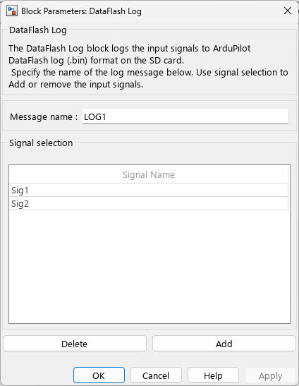
Block Parameters dialog box for the DataFlash Log block, showing the message name box and signal selection table.

PX4 Autopilots: Use preconfigured WSL environment for PX4 development

You can now import a preconfigured Windows Subsystem for Linux (WSL) distribution to set up the PX4 development environment. The distribution includes Ubuntu 22.04 with the PX4 firmware source code, build toolchain, and required dependencies preinstalled, so you can build and deploy PX4 firmware from Simulink without performing a manual environment setup.

During hardware setup, select Import pre-configured Ubuntu distribution for PX4 in the Choose Ubuntu Distribution Option screen.
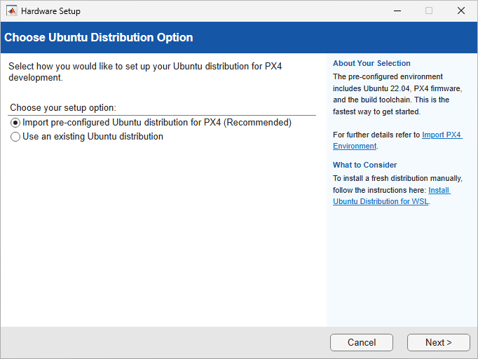
Hardware Setup screen showing Choose Ubuntu Distribution Option with Import pre-configured Ubuntu distribution for PX4 (Recommended) selected.

The wizard guides you through downloading, importing, and validating the preconfigured distribution. For more information, see Use Preconfigured WSL Environment for PX4.

 PX4 Autopilots: Support for PX4 Autopilot Firmware v1.16.1

The UAV Toolbox Support Package for PX4 Autopilots now supports PX4® Autopilot Firmware v1.16.1 for Ubuntu® 22.04 and Windows® platforms. Previous releases supported PX4 Autopilot Firmware v1.15.4.

For instructions on how to get the PX4 Autopilot Firmware v1.16.1 as part of the setup process of the UAV Toolbox Support Package for PX4 Autopilots, see Download PX4 Source Code in Windows Subsystem for Linux (WSL2).

PX4 Autopilots: Multi-instance uORB topic support

The UAV Toolbox Support Package for PX4 Autopilots now supports multi-instance uORB topics in the uORB Read and uORB Write blocks. uORB multi-instance topics allow multiple independent publishers of the same message type, such as multiple accelerometers, gyroscopes, or GPS receivers, to coexist under a single topic definition.

By default, each block uses instance 0 of the selected topic. To use a different instance, select Subscribe to other instances and specify the instance number. For more information, see PX4 uORB Read and PX4 uORB Write.

 PX4 Autopilots: MDF file logging support for Simulink signals

You can now log Simulink signals from PX4 targets directly to an SD card in a PX4 Autopilot board in Measurement Data Format (MDF), with the .mf4 extension. To enable MDF file logging, select Log signals to MDF file in the Interface pane of the Simulink model configuration parameters. For more details, see MDF File Logging on PX4 Autopilots.

MDF file logging is an alternative to MAT file logging. MDF file logging enables you to capture internal Simulink signals and supports large, time-synchronized datasets with minimal runtime overhead. For an example, see the MDF File Logging on SD Card for PX4 Autopilots example.
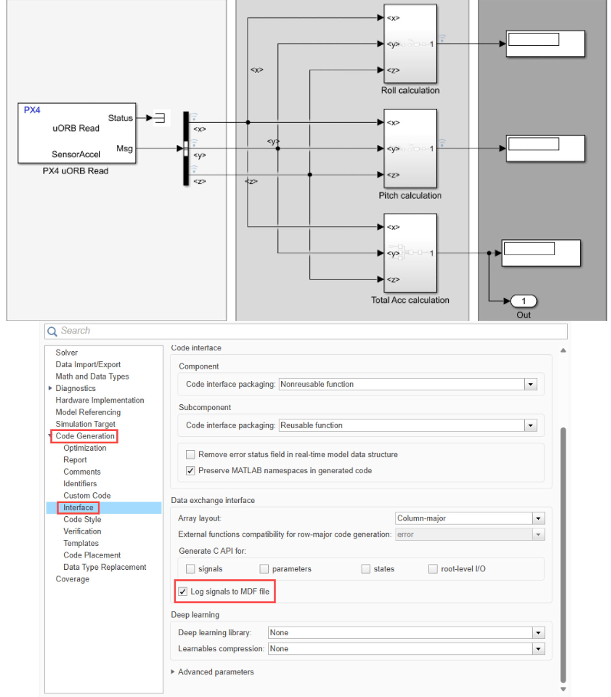
Log signals to MDF file option in Simulink.

 MAVLink Microservice Objects: Exchange heartbeats, commands, parameters, missions, and files with MAVLink clients

MAVLink microservice objects enable interaction with MAVLink‑based flight controllers from MATLAB®. The objects use MAVLink microservices to exchange heartbeat messages, parameters, commands, missions, and files with MAVLink compatible autopilots, such as PX4 and ArduPilot. Create MAVLink microservice objects by using the mavlinkmicroservice function.

These MAVLink microservice objects use standard MAVLink microservices:

Serial Connection Support for mavlinkio: Connect local MAVLink clients to serial ports

You can now use the connect object function of the mavlinkio object to connect a local MAVLink client to a serial port and specify serial connection settings, such as the port name and baud rate.

 addCustomTerrain Function: Control overwrite behavior for existing terrain names

When adding custom terrain data to a UAV scenario using the addCustomTerrain function, you can now specify how the function handles existing terrain names by using the NameExistsRule name‑value argument. When you specify a terrain name that already exists, the argument determines whether the function overwrites the existing data, preserves it, or returns an error.

 Compatibility Considerations

In previous releases, the addCustomTerrain function returned an error when you specified a terrain name that already existed. Starting in R2026b, you can return an error by specifying the NameExistsRule argument as "error".

3D Simulation updates

Simulation 3D Lidar Block: Configure surface reflection model

The Simulation 3D Lidar block now enables you to select a surface reflection model by setting the Reflection Model parameter to one of these options:

  • Phong — Models reflection as a linear combination of specular and diffuse values.

  • LambertianBeckman — Lidar-specific reflection model that incorporates local surface effects.

Simulation 3D Scene Configuration Block: Configure viewer and parent container

The Simulation 3D Scene Configuration block now enables you to select the 3D simulation viewer by setting the Choose viewer parameter to one of these options:

  • Default viewer — Opens the 3D simulation in the default Simulation 3D Viewer window.

  • UI Component — Embeds the 3D simulation viewer inside a UI container, such as a figure, panel, tab, or grid layout. Select the parent container by setting the Parent container parameter.

Migration to Cesium for Unreal 2.21.0

The UAV Toolbox Interface for Unreal Engine® Projects now supports Cesium® for Unreal® version 2.21.0. Previously, the interface supported Cesium for Unreal version 2.16.0.

Updated examples

Visualize and Play Back MAVLink Flight Log in 3D Scenario

The Visualize and Play Back MAVLink Flight Log in 3D Scenario example enables you to replay the flight paths of two UAVs in a 3D scenario using a specified time interval. This is an update to the Visualize and Play Back MAVLink Flight Log example in previous releases. For more details on 3D scenarios, see scenario (Mapping Toolbox).
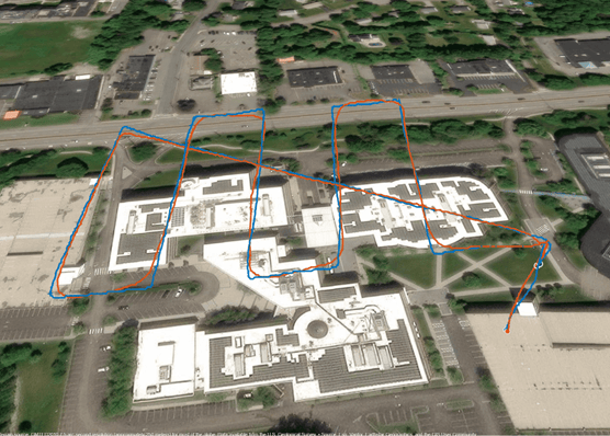
Two UAV flight paths displayed over buildings in a 3D scenario aerial view

Visualize PX4 Hardware-in-the-Loop (HITL) Simulation with UAV Dynamics in Simulink

The Visualize PX4 Hardware-in-the-Loop (HITL) Simulation with UAV Dynamics in Simulink example enables you to visualize your simulation using either Unreal Engine or 3D Scenarios. This is an update to the Scenario Simulation and Flight Visualization with PX4 Hardware-in-the-Loop (HITL) and UAV Dynamics in Simulink example in previous releases.

UAV Package Delivery

The UAV Package Delivery example has been updated so that the UAV now uses the MAVLink heartbeat microservice to establish a connection with QGroundControl.

 Functionality being removed or changed

PX4 Autopilots: Updated names for generic PX4 board options

Behavior change

The generic PX4 board options for the UAV Toolbox Support Package for PX4 Autopilots now have new names.

During the Select a PX4 Autopilot and Build Target step of hardware setup, you can now specify the PX4 Autopilot board as PX4 Generic Board. In previous releases, this option is My board is not listed here.

In the Simulink model configuration parameters, in the Hardware Implementation pane, you can now specify the Hardware board parameter as PX4 Generic Board. In previous releases, this value was PX4 Pixhawk Series.

The behaviors and settings associated with these options are unchanged.

PX4 Autopilots: Automatic detection of communication (COM) ports for PX4 generic boards

Behavior change

Simulink now automatically detects a correct communication (COM) port for all PX4 generic boards when flashing PX4 firmware and during host‑target communication. In previous releases, you had to manually specify the COM port.

R2026a

New Features, Compatibility Considerations

PX4 Autopilots: Use preconfigured WSL environment for PX4 development (July 2026, Version 26.1.7)

You can now import a preconfigured Windows Subsystem for Linux (WSL) distribution to set up the PX4 development environment. The distribution includes Ubuntu 22.04 with the PX4 firmware source code, build toolchain, and required dependencies preinstalled, so you can build and deploy PX4 firmware from Simulink without performing a manual environment setup.

During hardware setup, select Import pre-configured Ubuntu distribution for PX4 in the Choose Ubuntu Distribution Option screen.

Hardware Setup screen showing Choose Ubuntu Distribution Option with Import pre-configured Ubuntu distribution for PX4 (Recommended) selected.

The wizard guides you through downloading, importing, and validating the preconfigured distribution. For more information, see Use Preconfigured WSL Environment for PX4.

 PX4 Autopilots: Support for PX4 Autopilot firmware v1.15.4

Starting in R2026a, you can use the UAV Toolbox Support Package for PX4 Autopilots with PX4 Autopilot Firmware v1.15.4 for Ubuntu 22.04 and Windows platforms. Previous releases supported PX4 Autopilot Firmware v1.14.3.

PX4 Autopilots: Multi-instance uORB topic support (July 2026, Version 26.1.7)

The UAV Toolbox Support Package for PX4 Autopilots now supports multi-instance uORB topics in the uORB Read and uORB Write blocks. uORB multi-instance topics allow multiple independent publishers of the same message type, such as multiple accelerometers, gyroscopes, or GPS receivers, to coexist under a single topic definition.

By default, each block uses instance 0 of the selected topic. To use a different instance, select Subscribe to other instances and specify the instance number. For more information, see PX4 uORB Read and PX4 uORB Write.

 ArduPilot Autopilots: Run ArduPilot Software-in-the-Loop Simulation with Quadcopter Plant in Simulink

The Run ArduPilot Software-in-the-Loop Simulation with Quadcopter Plant in Simulink example shows how to deploy a quadcopter controller design to an ArduPilot host target, and simulate the quadcopter plant model in Simulink.
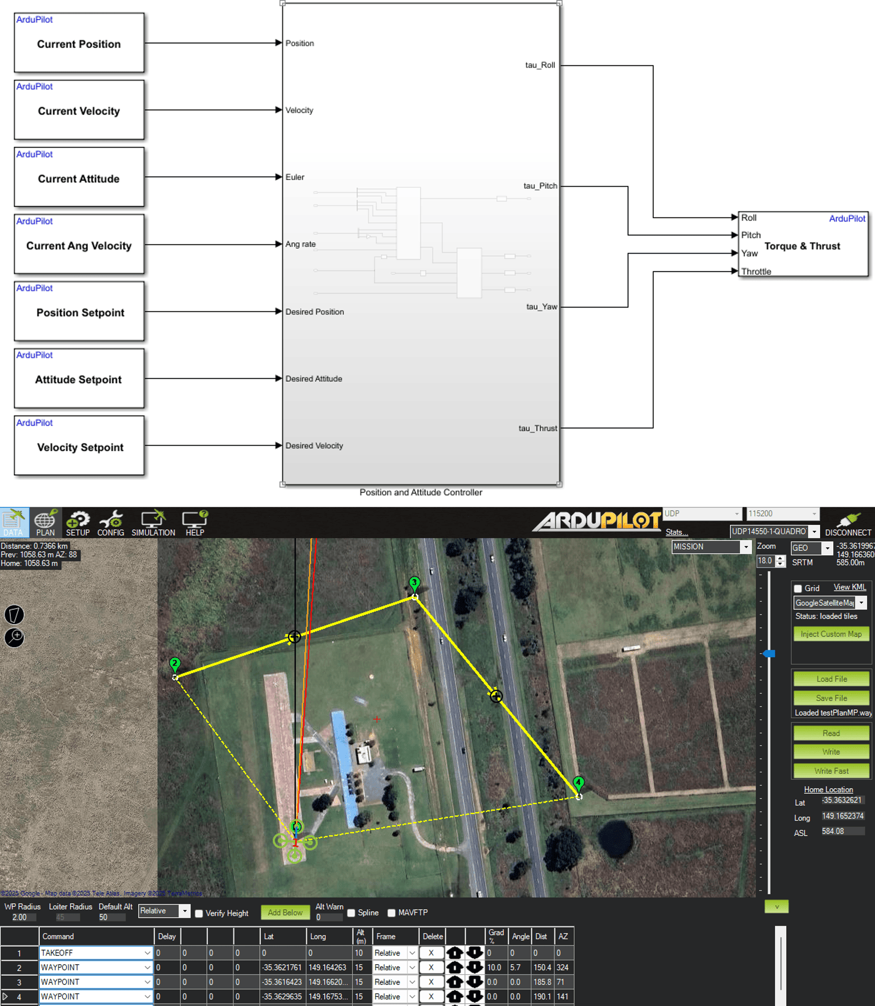
Quadcopter controller model and Mission Planner view of the mission.

Simulation 3D Custom UAV Pack Block: Generate translation and rotation inputs for custom UAV

Use the Simulation 3D Custom UAV Pack block to generate the translation and rotation inputs for a Simulation 3D UAV Vehicle block with Type set to Custom.

For an example of how to use the Simulation 3D Custom UAV Pack to generate translation and rotation inputs for a tilt-rotor VTOL UAV, see the Visualize VTOL UAV Takeoff and Forward Transition example.

 ulogreader Object: Improved performance when reading specified topic messages

The ulogreader object no longer reads all topic messages contained in the ULog file used to create the object. The object now only reads the topic messages that you specify when using the readTopicMsgs object function, which enables you to read the specified topic messages into the workspace faster.

For example, this code is approximately 4x faster than in the previous release:

function timingTest
  ulog = ulogreader("flight.ulg");
  message = readTopicMsgs(ulog,TopicNames="vehicle_attitude");
end

The approximate execution times are:

  • R2025B: 2.14 s

  • R2026A: 0.57 s

The code was timed on a Windows 11, Intel Xeon® CPU W-2133 @ 3.60 GHz test system using the timeit function:

timeit(@timingTest)

uavWaypointFollower System object: Disable yaw interpolation and output waypoint index

  • The uavWaypointFollower System object™ now allows you to disable the linear interpolation of the desired yaw between waypoints for a multirotor UAV by setting the InterpolateYaw property to false. In prior releases, the yaw interpolation is always enabled.

  • The System object now outputs the waypoint index of the current straight line segment using the new waypointIndex argument.

Waypoint Follower Block: Disable yaw interpolation and output waypoint index

  • The Waypoint Follower block now enables you to disable the linear interpolation of the desired yaw between waypoints for a multirotor UAV by setting the Yaw Interpolation parameter to off. In prior releases, the yaw interpolation is always enabled.

  • The block now enables you to output the waypoint index of the current straight line segment using the new Waypoint index port by selecting the Show Waypoint index output port parameter.
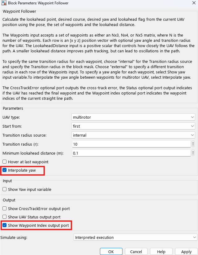
Interpolate Yaw and Show Waypoint Index output port parameters of the Waypoint Follower block.

UAV Animation Block: New parameters to set plot axis limits, maximum number of trajectory samples, and automatic opening of output figure

The UAV Animation block now has these new parameters:

  • Plot axis limits — Use this parameter to specify the axes limits of the output figure.

  • Max number of samples per trajectory — Use this parameter to specify the maximum number of samples that the block displays for each UAV trajectory.

  • Always open output figure at start of simulation — Select this parameter to configure the block to automatically open the figure when you start the simulation.
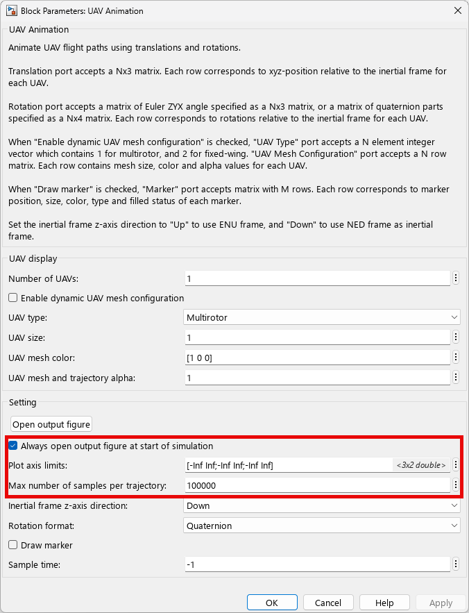
UAV Animation block mask, which shows the new parameters

minjerkpolytraj and minsnappolytraj Functions: Specify solver maximum iterations and solver maximum time, view solver status

The minjerkpolytraj and minsnappolytraj functions now enable you to specify the maximum number of iterations and maximum time of the solver by using the MaxNumIterations and MaxSolverTime name-value arguments, respectively.

To verify whether the solver reaches the maximum number of iterations, maximum solver time, or encountered singularity during optimization, see the status output argument.

UAV Coverage Space Visualization: Show or hide number labels

The show function of the uavCoverageSpace object now enables you to hide the number labels on polygons by specifying the ShowLabel name-value argument as false or 0. Previously, the function always displayed the number labels.
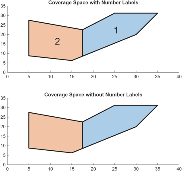
UAV Coverage Space visualization with and without number labels.

Coordinate Transformation Conversion Block Enhancements: Convert multiple coordinate transformations

You can now convert multiple coordinate transformations simultaneously to the specified output representation by using the Coordinate Transformation Conversion block. Given N coordinate transformations, where each transformation is a d-element column vector, you can specify a d-by-N matrix to the Input transformation port. If each transformation is an M-by-M matrix, specify an M-by-M-by-N array, instead.

Updated Examples

Run PX4 Software-in-the-Loop Simulation with Quadcopter Plant in Simulink

The "Monitor and Tune PX4 Host Target Flight Controller with Simulink-Based Plant Model" example has been renamed to Run PX4 Software-in-the-Loop Simulation with Quadcopter Plant in Simulink. The example now enables you to run a SITL simulation using a custom UAV mission that you created in QGroundControl.

Design and Tune Quadcopter Position Controller for PX4 Autopilot

The "Position Tracking for X-Configuration Quadcopter" example has been renamed to Design and Tune Quadcopter Position Controller for PX4 Autopilot . The controller model now contains step inputs that enables you to simulate the step responses of controller gains that you selected. The example also contains codes that you can run to plot and obtain the performance metrics of the step responses.

PX4 Hardware-in-the-Loop (HITL) Simulation with VTOL UAV

The HITL controller model of the PX4 Hardware-in-the-Loop (HITL) Simulation with VTOL UAV example now automatically determines the serial port for firmware upload, which enables you to deploy the code of the flight controller model without having to manually determine the COM port of your PX4 autopilot.

Visualize VTOL UAV Mission over Urban Environment

The photorealistic subsystem of the Visualize VTOL UAV Mission over Urban Environment example now uses the Simulation 3D Custom UAV Pack block to generate the rotation input for the tilt-rotor visualization of the VTOL UAV.

UAV Package Delivery

The multirotor subsystem of the UAV Package Delivery example has been updated to reduce the attitude change during land, and to ensure the multirotor achieves desired heading angle with minimum yaw. In addition, the UAV Package delivery model in the example now automatically ends the simulation after the multirotor lands.

 3D Simulation Updates

Coordinate System Parameter for Sensor Blocks

You can now set the Coordinate system parameter for these sensor blocks:

For more information on sensor coordinate systems, see Coordinate Systems for Unreal Engine Simulation in UAV Toolbox.

Interact with Actors and 3D Environment, Set Simulation Rendering Quality

You can now use the simulation 3D viewer interface to interact with the 3D environment and actors during simulation. The context menu enables you to select different views, show origins, save the 3D environment as MAT file, and create primitives. You can also use the context menu to set the simulation rendering quality to one of these options:

  • Auto — Best possible visual quality with current performance

  • Cinematic — ultra-high visual quality with slowest performance

  • Epic — Very-high visual quality with highest system requirements

  • High — High visual quality with high system requirements

  • Medium — Medium visual quality with low system requirements

  • Low — Lowest visual quality with lowest system requirements

For more information on using the simulation 3D viewer interface to interact with the 3D environment and actors, see Interact with 3D Simulation Environment.
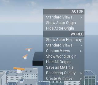
Actor and world context menu in simulation 3D viewer.

Simulation 3D Lidar: Configure the Lidar field of view to improve resolution in areas of interest within the 3D environment

The Simulation 3D Lidar block now enables you to sample the field of view of the sensor by setting the Field-of-view specification parameter to one of these options:

  • Symmetric — The field of view is centered along the forward direction of the lidar and extends equally in horizontal and vertical directions

  • Asymmetric — The field of view is not centered and it extends unequally in the positive and negative directions from the center.

  • Custom — The field of view is defined by sample angles.

Run Simulation in Blank Scene and Empty Scene

You can now run a UAV Unreal Engine scenario simulation in the Blank Scene and Empty Scene environments. The Blank Scene is a 3D environment without sky, default lighting, or objects. The Empty Scene is a 3D environment with a bright, open sky, clouds, and sunlight, but no objects.

To run the simulation in these scenes, add a Simulation 3D Scene Configuration block to your Simulink model, set the Scene source parameter to Default scenes, and then set the Scene name parameter to Blank scene or Empty scene.

Migration to Cesium for Unreal 2.16.0

The UAV Toolbox Interface for Unreal Engine Projects now supports Cesium for Unreal version 2.16.0. Previously, the interface supported Cesium for Unreal version 2.7.1.

Migration to Unreal Engine 5.4

The 3D visualization engine used by UAV Toolbox has been updated to Unreal Engine 5.4. Previously, the toolbox used Unreal Engine 5.3.

If your Simulink model uses an Unreal Engine executable or project developed using a prior release of the UAV Toolbox Interface for Unreal Engine Projects, the simulation can return an error.

To migrate the project so that it is compatible with the R2026a version of the support package, see Migrate Projects Developed Using Prior Support Packages.

 Compatibility Considerations

If your Simulink model uses an Unreal Engine executable or project developed using a prior release of the UAV Toolbox Interface for Unreal Engine Projects, the simulation can return an error.

To migrate the project so that it is compatible with the R2026a version of the support package, see Migrate Projects Developed Using Prior Support Packages

 Functionality being removed or changed

PX4 uORB Write Block: Length of publish queue parameter has been removed

Behavior change

Starting in R2026a, the Length of publish queue parameter of the PX4 uORB Write block has been removed. You no longer need to specify the queue size because the support package can now use PX4 Firmware v1.15.4, which internally allocates the queue size.

UAV Animation Block: Animate UAV in ENU coordinate system

Behavior change

The output figure of UAV Animation block now displays the UAV animation in the east-north-up (ENU) coordinate system for all input coordinate frame that you specify using the Inertial frame z-axis direction parameter. Prior to R2026a, the block animates in west-north-up coordinate system if you set the Inertial frame z-axis direction parameter to Down.
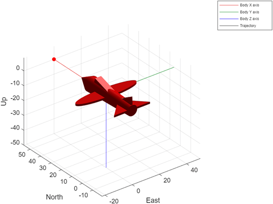
Output of UAV Animation block in ENU coordinate system

mavlinkio Object: Warning for invalid XML file

Behavior change

The mavlinkio object now displays a warning if you create the object using an XML file that does not contain a MAVLink message definition. Previously, the object did not display a warning if you created the object using an invalid XML file.

uavCoverageSpace Object: Specify UseLocalCoordinates as numeric 1 or 0

Behavior change

You can now specify the UseLocalCoordinates property of the uavCoverageSpace object as a numeric 1 to use local coordinates and as a numeric 0 to use geodetic coordinates. In previous releases, the property accepts only logical 1 (true) or 0 (false).

R2025b

New Features, Bug Fixes

Quality and stability improvements

R2025b delivers quality and stability improvements, building on the new features introduced in R2025a.

 UAV Toolbox Support Package for ArduPilot Autopilots: Design, simulate, and deploy flight control algorithms on ArduPilot autopilots

The UAV Toolbox Support Package for ArduPilot Autopilots enables you to design and simulate control algorithms in Simulink, generate code for those algorithms using Embedded Coder®, and integrate the generated code with ArduPilot. You can run your models in software-in-the-loop (SITL) mode, or deploy them to supported ArduPilot-based autopilots.

The support package includes these features:

  • Simulink block support — Use Simulink blocks to read and write flight-related data such as sensor readings, actuator commands, setpoints, and RC input.

  • Support for Connected I/O mode — Communicate with ArduPilot autopilot peripherals in real-time.

  • Support for Monitor & Tune mode — Monitor signals and tune parameters of ArduPilot autopilot.

  • Deployment of flight control algorithms — Deploy algorithms developed in Simulink directly onto ArduPilot-based autopilots.

  • Support for multiple vehicle types — Develop algorithms for both ArduCopter and ArduPlane firmware, enabling development for a range of aerial vehicles that includes multirotors and fixed-wing aircraft.

  • Algorithm validation with software-in-the-loop (SITL) simulation — Validate control algorithms using ArduPilot SITL host target simulation, enabling you to test reliability and performance under various simulated flight conditions before deploying to hardware.

The support package also includes these examples, which demonstrate its capabilities:

For more information on using UAV Toolbox with ArduPilot, see UAV Toolbox Support Package for ArduPilot Autopilots.

ardupilotreader Object: Improved performance when reading ArduPilot log file

The ardupilotreader object has improved performance when reading an ArduPilot log file.

For example, this code is approximately 2x faster than in previous release:

function timingTest
  arduObj = ardupilotreader("sampleArdupilotLog.bin");
end

The approximate execution times are:

  • R2025a: 8.18 s

  • R2025b: 4.17 s

The code was timed on a Windows 11, Intel Xeon CPU W-2133 @ 3.60 GHz test system using the timeit function:

timeit(@timingTest)
sampleArdupilotLog.bin is a sample ArduPilot log file with a size of 118MB. Replace sampleArdupilotLog.bin in the test code with your own ArduPilot log file of similar size to test the performance improvement.

R2025a

New Features, Compatibility Considerations

 Flight Log Signal Mapping Enhancements: Analyze EKF message from PX4 flight logs

The flightLogSignalMapping object has new predefined signals and plots that you can use to analyze EKF messages, such as for estimator status flags, EKF innovations, and wind estimates.

Use the mapulog function to map PX4 ULOG messages to the predefined signals.

Plot of magnetometer innovations

Simulation 3D UAV Vehicle Block Enhancement: Specify motor tilt angle and rotor angular velocity

The Simulation 3D UAV Vehicle block can now simulate a custom tilt-rotor UAV with a specified motor rotation angle and rotor angular velocity for up to eight motor-rotor pairs.

For an example on how to visualize a tilt-rotor UAV in vertical takeoff and forward transition phase, see Visualize VTOL UAV Takeoff and Forward Transition.
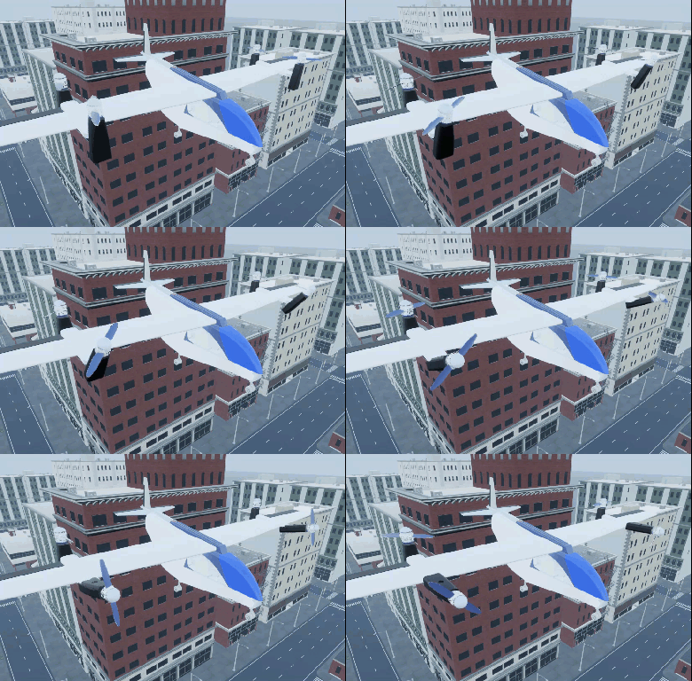
Tilt-rotor UAV animation

Multi-UAV Simulation: Simulate multiple reduced-order UAV models in Simulink

Use the Multi-Instance Guidance Model block to simulate multiple small UAVs with reduced-order fixed-wing or multirotor kinematic models and autopilot controllers.
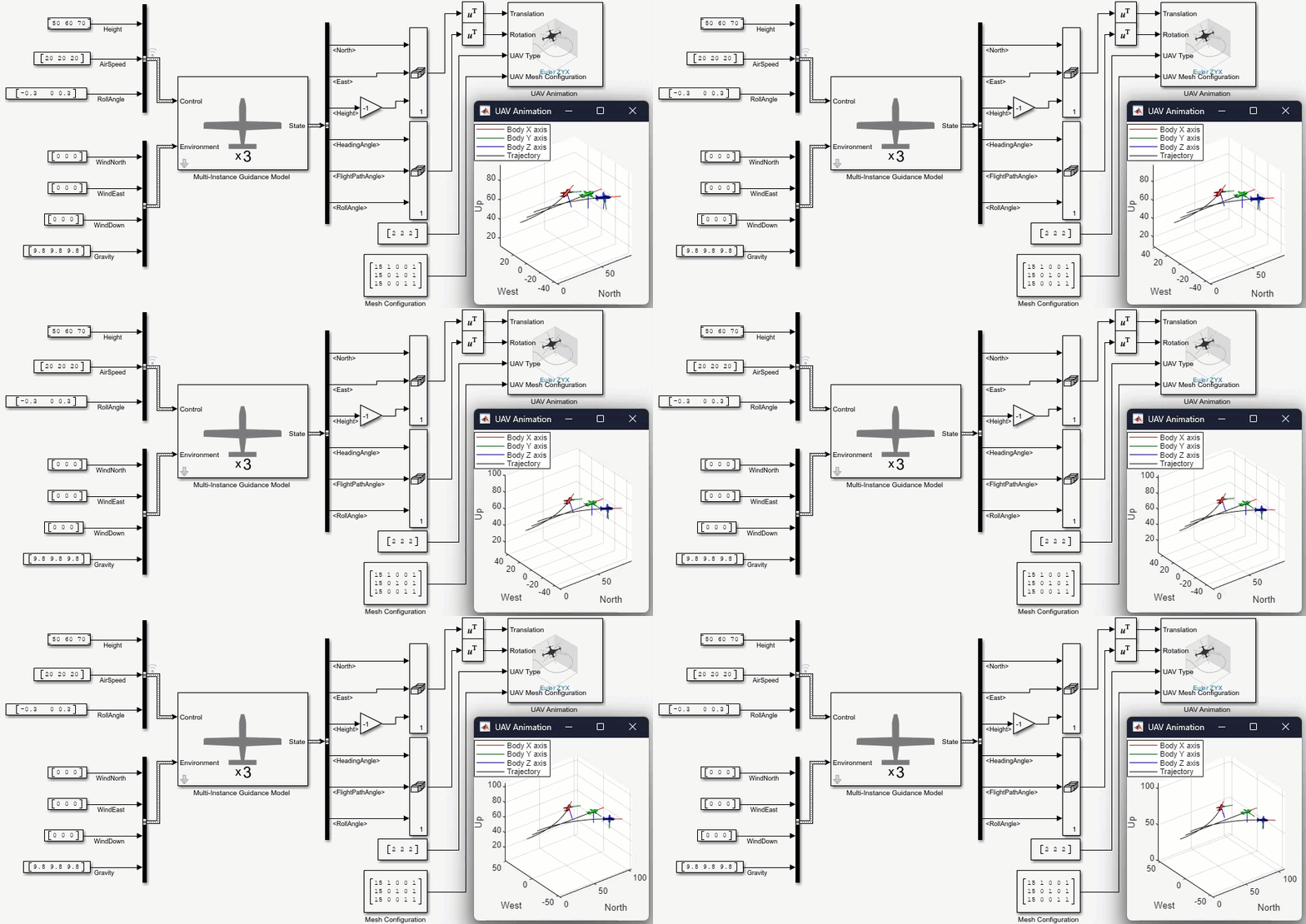
Animation of Simulink model with Multi-Instance Guidance Model block

Barometer Sensor: Generate air pressure reading with measurement noise

Use the barometerSensor System object or Barometer block to simulate a barometer sensor and generate air pressure readings with noise.
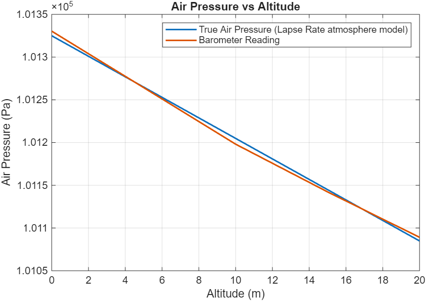
Plot of air pressure vs altitude

 VTOL UAV Controller Template: Battery sizing for mission over an urban environment

The VTOL UAV Controller Template now includes the new VTOL UAV Battery Sizing for Mission Over an Urban Environment example, which demonstrates how to select a battery size that maximizes the range of an eVTOL UAV for a mission over an urban environment..
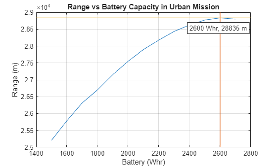
Plot of range vs battery capacity.

PX4 Autopilots: Generate PX4 CUAV X7+ autopilot code

You can now use the UAV Toolbox Support Package for PX4 Autopilots to generate code for the CUAV X7+ autopilot.

To configure Simulink to generate code for the PX4 CUAV X7+ autopilot, open the model Configuration Parameters dialog box, select Hardware Implementation, and set Hardware board to PX4 CUAV X7+.

 PX4 Autopilots: Support for simulation-in-hardware (SIH)

The UAV Toolbox Support Package for PX4 Autopilots now includes support for the simulation-in-hardware (SIH) mode. This feature enables you to execute Simulink-generated code directly on the PX4 Host Target, enabling testing and validation of control algorithms in a simulated environment.

For more information on how to set up an SIH simulation, see Deployment and Verification Using PX4 Host Target and jMAVSim/Simulink.

 PX4 Autopilots: Support for PX4 Autopilot firmware v1.14.3

The UAV Toolbox Support Package for PX4 Autopilots now supports PX4 Autopilot firmware v1.14.3 for both Ubuntu 18.04 and Windows platforms. Previously, the support package supported PX4 Autopilot Firmware v1.14.

PX4 Autopilots: PX4 Write Thrust & Torque Setpoint block

Use the PX4 Write Thrust & Torque Setpoint block to write motor and servo actuator values by directly publishing thrust and torque setpoints to the vehicle_thrust_setpoint and vehicle_torque_setpoint uORB topics.

PX4 Autopilots: PX4 Write Parameter block

Use the PX4 Write Parameter block in your Simulink model to write directly to PX4 parameters, enabling you to easily modify parameters.

New examples

This release contains these new examples:

Quaternion Object: Use interp1 to interpolate quaternions

Use the interp1 object function of the quaternion object to interpolate quaternions using interpolation methods such as SQUAD and SLERP.

This figure visualizes interpolated quaternions on a unit sphere by using the sample and interpolated quaternions to rotate a 3-D point. The annotated numbers on the points are the sample points and query points that correspond to v and vq, respectively.

Interpolated quaternions visualized using rotated points on a unit sphere.

Quaternion Object: slerp function supports natural interpolation

The slerp object function of the quaternion object now supports spherical interpolation using the "natural" path option, which avoids the shortest path optimization, resulting in a longer path around the unit sphere that respects the orientation of the start and end quaternions.

This figure visualizes the difference between the "short" and "natural" interpolation methods by rotating a point using the interpolated quaternions on a unit sphere.

Visualization of the difference between the "short" and "natural" interpolation methods by rotating a point using the interpolated quaternions on a unit sphere.

3D Simulation Updates

Simulation 3D Scene Configuration Block Enhancements

  • Offline Tileset Support — The Simulation 3D Scene Configuration block now supports offline tilesets in 3D simulation. To use offline tileset data, specify the TilesetSource parameter as URL, and specify the URL parameter as the file path of your offline tileset data.

    You can also specify the TilesetSource and URL properties when creating a sim3d.environment.GeospatialConfiguration object.

  • Multiple Custom Views — You can now create and save multiple custom views of the 3D environment when using the Simulation 3D Scene Configuration block.

    The Custom option for the Scene view parameter now provides these parameters to customize the view.

    • Name

    • Translation

    • Rotation

    To save the custom viewpoint, click Save. Select the custom view from the Scene view parameter to set the view of the 3D environment. You can also edit the viewpoint, or click Delete to delete the viewpoint.

  • USD Format Support — The Simulation 3D Scene Configuration block now supports importing scenes with the Universal Scene Description (USD) file format.

  • Download and Install Scenes — You can now install prebuilt scenes from the Simulation 3D Scene Configuration block. For more details the prebuilt scenes, license requirements, and installation steps, visit 3D Scenes for Simulation in Unreal Engine Environment.

Simulation 3D Camera Block Enhancement

You can now visualize the camera coverage of the Simulation 3D Camera block by using the Visualize field of view and Field of view range parameters.
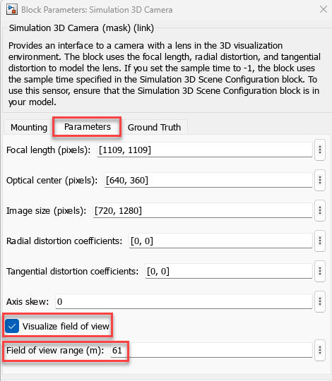
Block mask settings to visualize field of view and set the field of view range

Migration to Cesium for Unreal 2.7.1

The UAV Toolbox Interface for Unreal Engine Projects now supports Cesium for Unreal version 2.7.1.

MathWorks Geospatial Plugin No Longer Enabled by Default

Behavior change

When you install the UAV Toolbox Interface for Unreal Engine Projects and copy the support package files by using copyExampleSim3dProject, the MathWorks Geospatial plugin is not enabled by default. You must enable this plugin to stream 3D map and terrain data of a location using Cesium Ion®. For more information, see Install Cesium for Unreal Plugin and Visualize with Cesium.

R2024b

New Features, Compatibility Considerations

 VTOL UAV Controller Template: Tune hover control design in steady wind condition

The VTOL UAV Controller Template has been updated with a new example that demonstrates how to improve the hover performance of the Vertical Take-Off and Landing (VTOL) UAV by tuning the hover control design in the presence of a constant wind. For more information, visit Tune Hover Control Design for VTOL UAV in Steady Wind Condition.
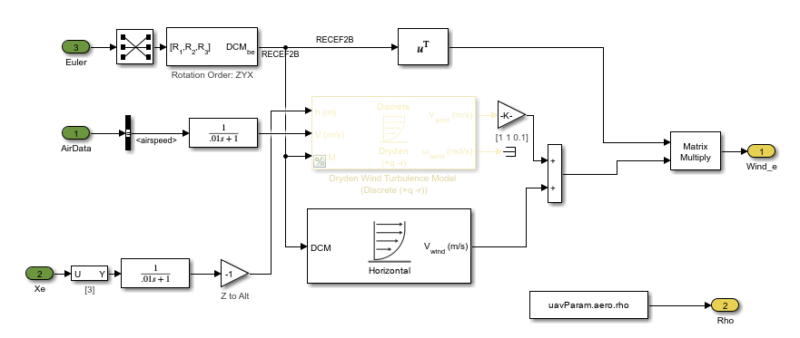
Wind model blocks in VTOL UAV controller template

UAV Scenario and 3D Simulation Integration: Design flight trajectories for 3D simulation in UAV scenario

The addMesh function of the uavScenario object now supports adding Suburban or US City Block scenes to a UAV scenario for flight trajectory design. Import trajectories into the 3D simulation environment in Simulink using the Read UAV Trajectory block.

For an example, see Simulate UAV Scenario Trajectory in Unreal Engine Environment.
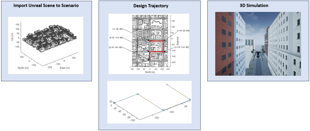
Process of importing Unreal scene into UAV scenario, designing a trajectory in the scenario, and simulating the trajectory in the 3D Unreal scene.

UAV Formation Metrics: Evaluate UAV formation quality

Evaluate UAV formation quality in applications, such as drone shows, agricultural missions, etc. by creating a uavFormationMetrics object and using the metrics function to obtain connectivity, order, safety, and union metrics. Obtain formation graphs and inter-UAV distances by using the formationInfo function.
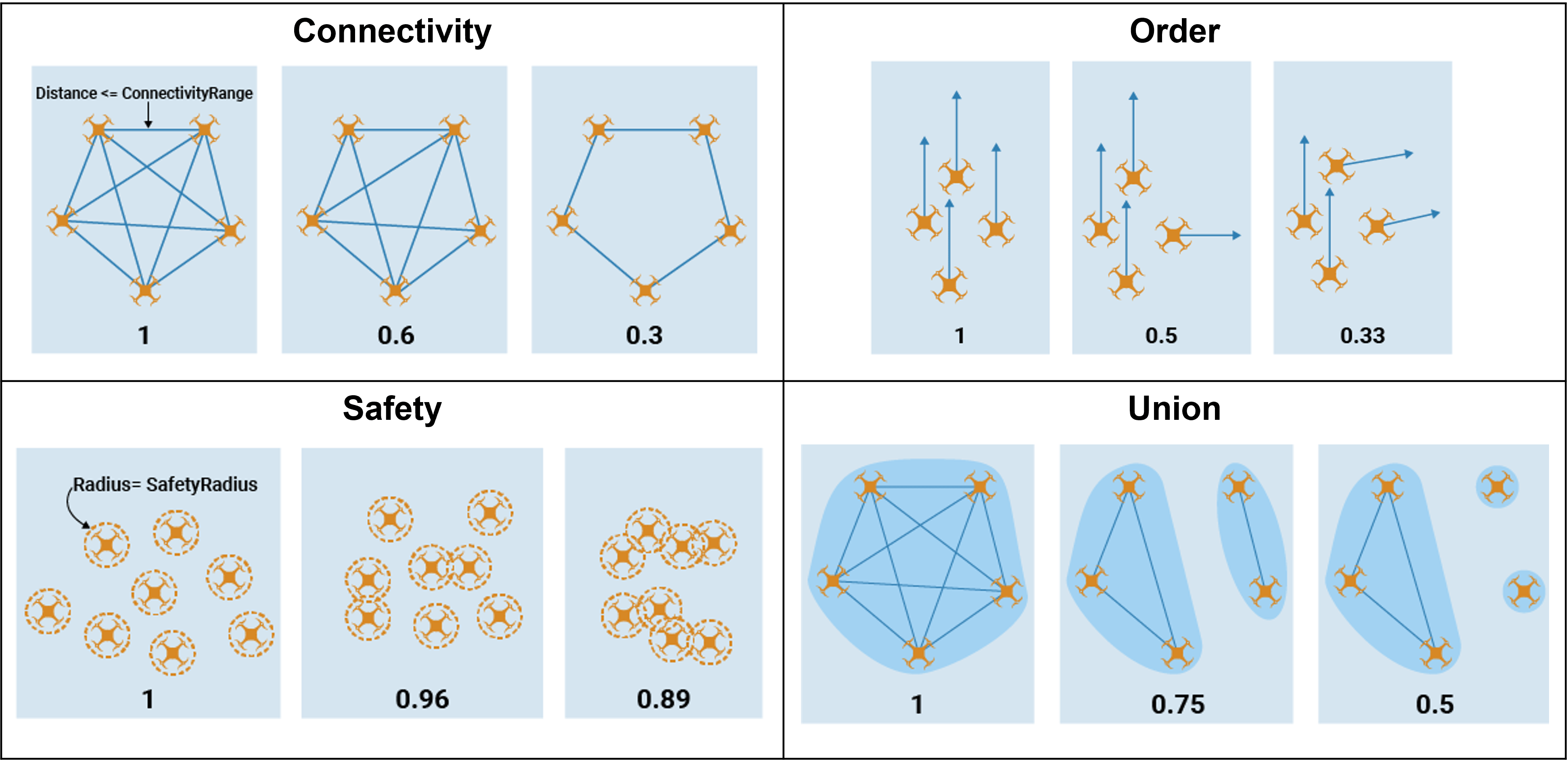
UAV formation performance metrics

UAV Animation Block Enhancements: Visualize multiple UAVs and markers

You can now use the UAV Animation block to visualize multiple UAVs and markers. For an example of using markers to visualize the lookahead point of a waypoint-following controller, see the Tuning Waypoint Follower for Fixed-Wing UAV example.
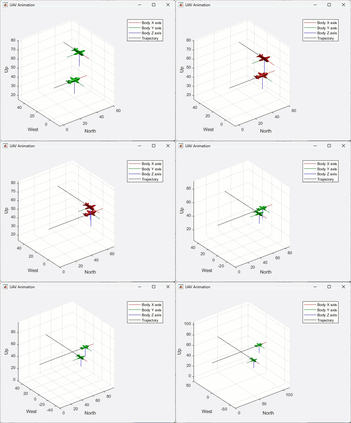
uav animation

PX4 Autopilots: Generate PX4 Cube Blue H7 autopilot code

You can now use the UAV Toolbox Support Package for PX4 Autopilots to generate code for the Cube Blue H7 autopilot.

To configure Simulink to generate code for the Cube Blue H7 autopilot, open the model Configuration Parameters dialog box, select Hardware Implementation, and set Hardware board to PX4 Cube Blue H7.

 PX4 Autopilots: Set actuator values for motors and servos using PX4 Actuator Write block

Starting in R2024b, you can use the PX4 Actuator Write block in your Simulink model to write motor and servo actuator values over the PWM and UAVCAN interfaces. This block is available in the PX4 Peripheral Blocks library in the UAV Toolbox Support Package for PX4 Autopilots.
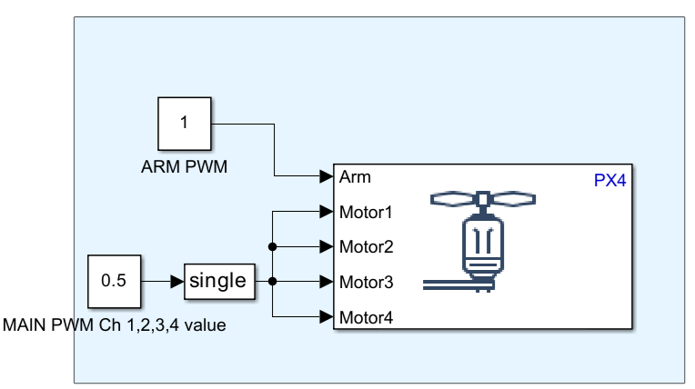
Model with PX4 actuator write block

 Video Send Block: GStreamer installation required (November 2026)

The Video Send block now uses a GStreamer distribution that you must install separately from UAV Toolbox, enabling you to select a GStreamer version and manage updates to it independently.

 Compatibility Considerations

In previous releases, Simulink models using the Video Send block ran without requiring a separate GStreamer installation because GStreamer was installed with UAV Toolbox. You must now install GStreamer separately to run these models.

 New Example: Simulate Multiple Fixed-Wing UAVs in Simulink Using System Objects

This release contains a new example on how you can simulate multiple UAVs in a waypoint following mission. Use this example as a reference to simulate formation flights, swarm mission, and other missions that requires simulating multiple UAVs. For more information, visit Simulate Multiple Fixed-Wing UAVs in Simulink Using System Objects
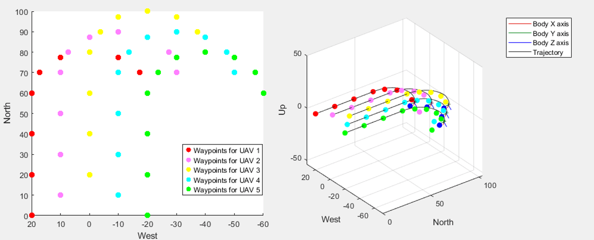
Waypoints for 5 UAVs and the plot of simulation result

Example Update: Survey Urban Environment Using UAV

The Survey Urban Environment Using UAV example has been updated to provide more information on how to calculate the coverage width of the camera.
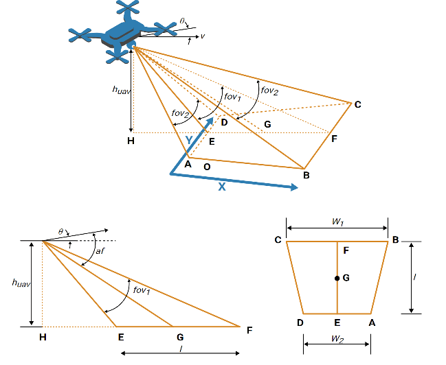
Relationship between field of view, UAV height, and coverage area.

 3D Simulation Updates

  • Stream 3D maps using the new Geospatial Configuration API

    Use the new sim3d.environment.GeospatialConfiguration API to stream 3D maps and configure the Cesium® ion™ stream in Simulation 3D MATLAB simulations..

  • Customize Unreal Engine Scenes on Linux® Platforms

    You can now customize Unreal Engine scenes using Linux platforms. For more detail on how to configure your environment, visit Configure Environment on Linux Platforms.

  • Migration to Unreal Engine 5.3

    The 3D visualization engine that is used in UAV Toolbox has been updated to Unreal Engine 5.3. Previously, the toolbox used Unreal Engine 5.1.

 Compatibility Considerations

If your Simulink model uses an Unreal Engine executable or project developed using a prior release of the UAV Toolbox Interface for Unreal Engine Projects support package, the simulation can return an error.

To migrate the project so that it is compatible with the R2024b version of the support package, see Migrate Projects Developed Using Prior Support Packages.

 Functionality being removed or changed

PX4 Autopilots: PX4 PWM Output block will be removed

Still runs

The PX4 PWM Output block is not recommended for use and will be removed in a future release. Use the PX4 Actuator Write block instead.

R2024a

New Features, Compatibility Considerations

 VTOL UAV Controller Template: Deployment to PX4 hardware

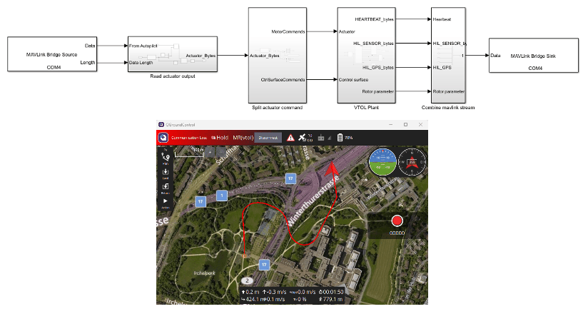
You can now deploy the VTOL UAV controller template to PX4 hardware for Hardware-in-the-Loop (HITL) simulation. For more information, see PX4 Hardware-in-the-Loop (HITL) Simulation and Visualization with VTOLHITL simulation and model
 UAV Scenario: Simulate wind effect on UAV platforms

You can now model wind effects in a UAV scenario by creating uavWindSteady, uavWindGust, or uavWindTurbulence objects, then adding the wind object to the UAV platform using addWind function. Obtain the wind velocity in the UAV platform body frame by using the windVelocity function while scenario simulation is running. Generating wind samples for UAV platform in MATLAB requires an Aerospace Toolbox license. Generating wind samples for a UAV platform in Simulink requires an Aerospace Blockset™ license.
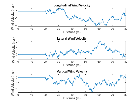
Sample wind in UAV scenario

ArduPilot Log Support: Read ArduPilot logs into Flight Log Analyzer app and MATLAB

The Flight Log Analyzer app now enables you to import ArduPilot dataflash log files (.bin). On the app toolstrip, select Import > From BIN to load an ArduPilot log file. You can also read ArduPilot log files into MATLAB by using the ardupilotreader object.

Flight Log Analyzer App: Visualize trajectory and UAV attitude on 3D map

You can now use the Flight Log Analyzer app to visualize the flight trajectory and attitude of a UAV in 3D by enabling 3D Map from the app toolstrip. The 3D map requires a Mapping Toolbox™ license.
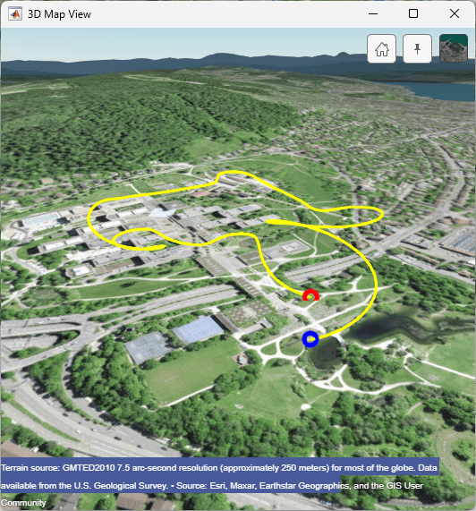
Flight log analyzer app showing the 3D map

 PX4 Autopilots: Support for PX4 Autopilot Firmware v1.14

UAV Toolbox Support Package for PX4 Autopilots now supports PX4 Autopilot Firmware v1.14 for both Ubuntu 18.04 and Windows platforms. The support package supported v1.12.3 until R2023b.

 PX4 Autopilots: Support for PX4 Cube Orange Plus and Pixhawk 6c autopilot

You can now use UAV Toolbox Support Package for PX4 Autopilots to generate code for the Cube Orange Plus and Pixhawk® 6c autopilots.

To generate the code, in the Configuration Parameters dialog box, select Hardware Implementation, and under Hardware board select PX4 Cube Orange+ or PX4 6c.

PX4 Autopilots: CAN Transmit and CAN Receive blocks to support STM32H7-based autopilots

The CAN Transmit and CAN Receive blocks from UAV Toolbox Support Package for PX4 Autopilots now support transmitting and receiving messages through the CAN port on STM32H7 microcontroller-based autopilots such as Cube Orange, Cube Orange Plus, Pixhawk 6x, and Pixhawk 6c.

PX4 Autopilots: Support package documentation moved into UAV Toolbox documentation

Starting in R2024a, the UAV Toolbox Support Package for PX4 Autopilots documentation is included in the UAV Toolbox product documentation and all support package updates are announced in the UAV Toolbox release notes. In previous releases, the support package documentation installed with the support package software. To access the archived release notes from previous support package releases, see PX4 Autopilots R2023b Release Notes.

Simulation 3D Scene Configuration Block: Use additional weather configurations to simulate adverse weather conditions

Starting in R2024a, you can configure the Simulation 3D Scene Configuration block to design enhanced weather scenarios within a 3D visualization environment. Additional weather configurations include:

  • Sun position based on geolocation

  • Snowfall conditions

  • Volumetric cloud parameters

  • Raindrop interaction on camera sensors

 3D Visualization: Simulating models in 3D environment requires Simulink 3D Animation

Starting in R2024a, simulating models with these Simulation 3D blocks requires Simulink 3D Animation™. The blocks allow Simulink software to integrate with Unreal Engine so that you can interrogate the world around the vehicle for virtually testing perception, control, and planning algorithms.

 Compatibility Considerations

Simulating models and interfacing with Unreal Engine in the 3D environment requires Simulink 3D Animation.

  Unreal Engine Simulation Upgrade: Run 3D simulations using Unreal Engine 5.1

The 3D visualization engine that comes installed with UAV Toolbox has been updated to Unreal Engine 5.1. Previously, the toolbox used Unreal Engine 4.27.

For information about using Unreal Engine to create custom scenes, see Customize Unreal Engine Scenes for UAVs and Unreal Engine Simulation Environment Requirements and Limitations.

 Compatibility Considerations

If your Simulink model uses an Unreal Engine executable or project developed using a prior release of the UAV Toolbox Interface for Unreal Engine Projects support package, the simulation may return an error. To migrate the project so that it is compatible with the R2024a version of the support package, see Migrate Projects Developed Using Prior Support Packages.

Unreal Engine Simulation Upgrade: Run 3D simulations on Linux platforms

The 3D visualization engine that comes installed with UAV Toolbox has been updated to run on Linux platforms. Previously, the 3D visualization ran on only Windows platforms.

For more information, see Unreal Engine Simulation Environment Requirements and Limitations.

Suburban Scene Stencil ID

The Suburban scene asset now has a stencil ID that enables you to perform semantic segmentation using the Simulation 3D Camera block. For an example of semantic segmentation in a UAV simulation, see Depth and Semantic Segmentation Visualization Using Unreal Engine Simulation.
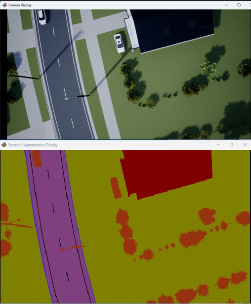
Semantic segmentation in suburban scene

New Example: Simulate UAV Waypoint Following with Different Wind Conditions

This release contains a new example on how to simulate a UAV Scenario with different wind conditions. For more information, visit Simulate UAV Waypoint Following with Different Wind Conditions Trajectories under different wind conditions
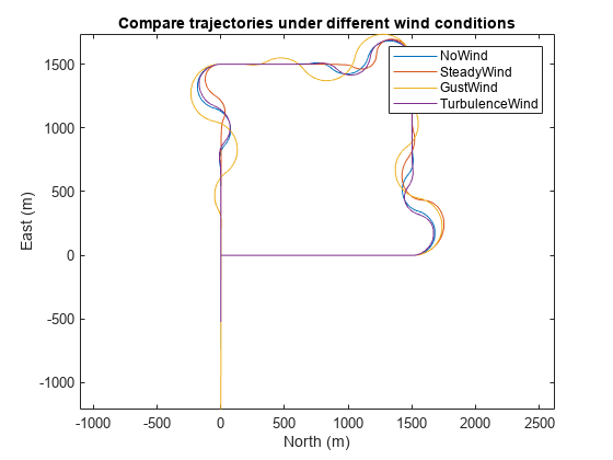
Example Update: Simulate Safe Landing of UAV in Unexplored Environment Using Unreal Engine

The Simulate Safe Landing of UAV in Unexplored Environment Using Unreal Engine example has been updated to provide more information on the Stateflow chart, 3D lidar sensor, and the plant and controller model used in the example.

R2023b

New Features

Additional uavSensor Support: Simulate GNSS measurement generator

The uavSensor object now supports the gnssMeasurementGenerator (Navigation Toolbox) System object as a sensor model to simulate global navigation satellite system (GNSS) receiver measurements in a UAV scenario. This feature requires Navigation Toolbox™.

Lidar Simulation Performance Improvements: Faster simulation of UAV scenario with lidar sensor

The uavLidarPointCloudGenerator now has improved simulation performance in UAV scenarios with high numbers of meshes.

These are the times required in the previous and current versions to generate 50 point cloud readings at a resolution of 32-by-1083-by-3 points using a UAV scenario centered on New York City with approximately 650 buildings and terrain meshes:

R2023a: 78.54 s

R2023b: 4.43 s

These simulations were timed on a Windows 10 system with a 3.2GHz AMD® EPYC™ 74F3 CPU with 48 GB of RAM and an NVIDIA® A16 GPU.

Simulation 3D Scene Configuration Block: Camera view improvements, including controls for visualizing the virtual world

The Simulation 3D Scene Configuration block now provides the option to view the virtual world scene from a camera positioned at a custom viewpoint. To set the custom viewpoint, set Scene view parameter to Custom and specify the Initial viewer translation and Initial viewer rotation to position the camera at the specified location. When the simulation starts, you can view the virtual world in a free camera mode at the specified viewpoint.

When the Scene view parameter is set to Scene Origin or Custom, you can use keyboard shortcuts and mouse controls for camera features, including to record camera viewpoints, attach camera to actors, and orbit around the actor. You can also control the camera when the simulation is paused.

Simulation 3D Scene Configuration Block: Import RoadRunner scene as Unreal Engine scene

The Simulation 3D Scene Configuration block now provides the option to simulate custom scenes built in RoadRunner. Use the Scene source parameter to specify the source of scene as RoadRunner. Then, in the Project parameter, specify the Filmbox (.fbx) file corresponding to the desired RoadRunner scene. You can obtain the Filmbox (.fbx) file by exporting the scene from RoadRunner.

For an example on how to import a RoadRunner scene in to Unreal Engine simulation environment, see Import RoadRunner Scene into Unreal Engine Using Simulink (Simulink 3D Animation).

Flight Log Analyzer: Export signal with time cropping and resampling

The Flight Log Analyzer app now enables you to crop and resample the signal that you choose to export in the Export Signal dialog box. To crop the signal, enable the Time Cropping option and specify the time cropping limits. To resample the signal, enable the Sampling Rate option and specify the sampling rate in Hz.
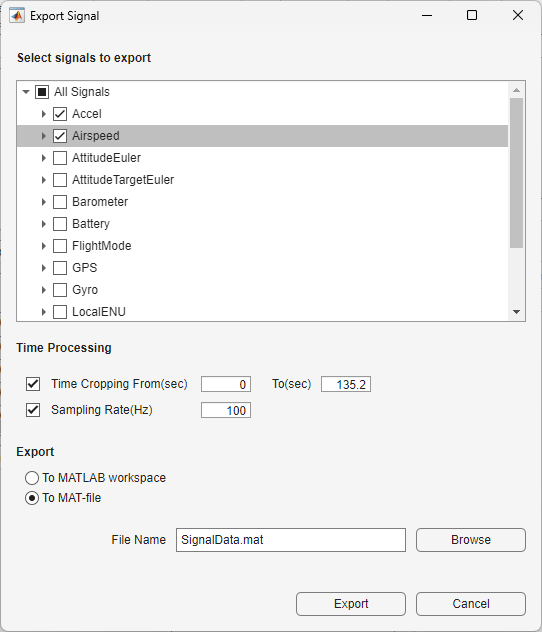
New option to crop and resample exported signal in Flight Log Analyzer

PX4 Support Package Updates

VTOL UAV Controller Template

Use the Design and Tune Controller for VTOL UAV to design and tune a vertical takeoff and landing (VTOL) UAV using a reference application template as a MATLAB Project
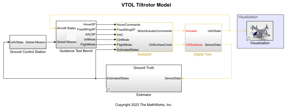
Updated example

This release contains enhancement to the following examples:

R2023a

New Features, Bug Fixes

UAV Coverage Planner: Plan paths to survey regions with UAV

Use the UAV coverage planner object, uavCoveragePlanner, to plan optimal paths through regions of interest and export the waypoints to a .txt or .waypoints file. Use the uavCoverageSpace object to define a region as a coverage space. You can use these objects to capture data of defined regions using onboard UAV sensors, such as a camera, for applications such as precision agriculture, area surveying, and image mapping.
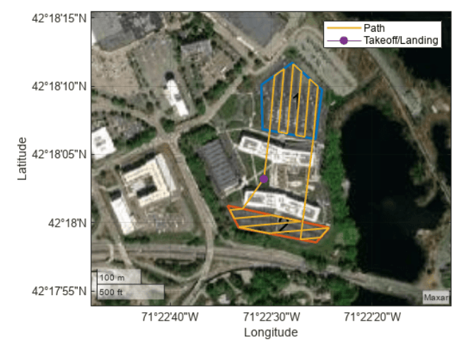
UAV coverage plan of a small island shown on a map

Sign MAVLink Messages: Protect UAVs from unauthorized communication with signing keys

Use the addmavlinkkeys object function to import signing keys from .env files into the MATLAB session. You can use signing keys to protect your UAVs from unauthorized communication.

Use the mavlinksigning object to create signing channel, which can be used in mavlinkdialect object to add signature to MAVLink packets.

Simulation 3D Ultrasonic Sensor Block: Generate synthetic range measurements in Unreal Engine scenarios

The Simulation 3D Ultrasonic Sensor block generates synthetic range measurements in a simulation environment rendered using the Unreal Engine from Epic Games®. The block includes parameters for sensor mounting and field of view.

You can use the ultrasonic sensor for detecting obstacles around a UAV during flight and use that sensor data in an obstacle-avoidance algorithm to avoid collisions.

Support for Cesium Plugin: Stream 3D maps and terrain data using Cesium Ion

UAV Toolbox can now stream 3D map and terrain data of a location using Cesium Ion. UAV Toolbox uses Unreal Engine to visualize your simulation, and then uses Cesium to create a scene for that visualization at runtime. To customize Cesium scenes, download the Cesium for Unreal visualization platform and use the UAV Toolbox Interface for Unreal Engine Projects support package.

To support this new capability, the Simulation 3D Scene Configuration block has been updated with a new Geospatial parameters tab that contains options for configuring the Cesium ion stream.

Transformation and Rotation Conversion Support: Use additional conversions for SE(2), SE(3) transformations and SO(2), and SO(3) rotations

The se2, se3, so2, and so3 objects now support these additional conversions to and from other rotation or transformation representations, such as Euler angles, quaternions, and axis-angle vectors using these objects and object functions

In addition, these existing conversion functions now support 2-D inputs in addition to 3-D inputs:

Piecewise-Polynomial Trajectory Interface: Create piecewise-polynomial trajectories in scenario simulation

Use the polynomialTrajectory System object to generate trajectory using piecewise-polynomial in a scenario simulation.

You can create a piecewise-polynomial structure using trajectory generators like minjerkpolytraj, and minsnappolytraj, as well as any custom trajectory generator. You can then pass the structure to the polynomialTrajectory System object to create a trajectory interface for scenario simulation using the uavScenario object.

You can now use the polynomialTrajectory object to specify the trajectory for uavPlatform motion.

Piecewise-Polynomial Trajectory Interface Support on UAV Scenario Designer App: Create piecewise-polynomial trajectories in UAV Scenario Designer

The UAV Scenario Designer app now enables you to import custom trajectories generated using the polynomialTrajectory System object into a scenario for simulation. However, you cannot edit or create polynomialTrajectory System objects using the app.

Flight Log Analyzer: Flight Log Analyzer app enhancements

The Flight Log Analyzer app has been updated with these enhancements:

  • The Flight Log Analyzer app now enables you to add additional log signals from files of the supported formats (.ulog, and .tlog) from within the app. Custom signal mapping enables you to map any signal available in the log data within the app. You can specify signal names, scale the signal values, and provide signal units. Once you have successfully mapped a custom signal, you can visualize the signal using custom plots. Click Add Custom Signal to open the Add Custom Signal dialog box.
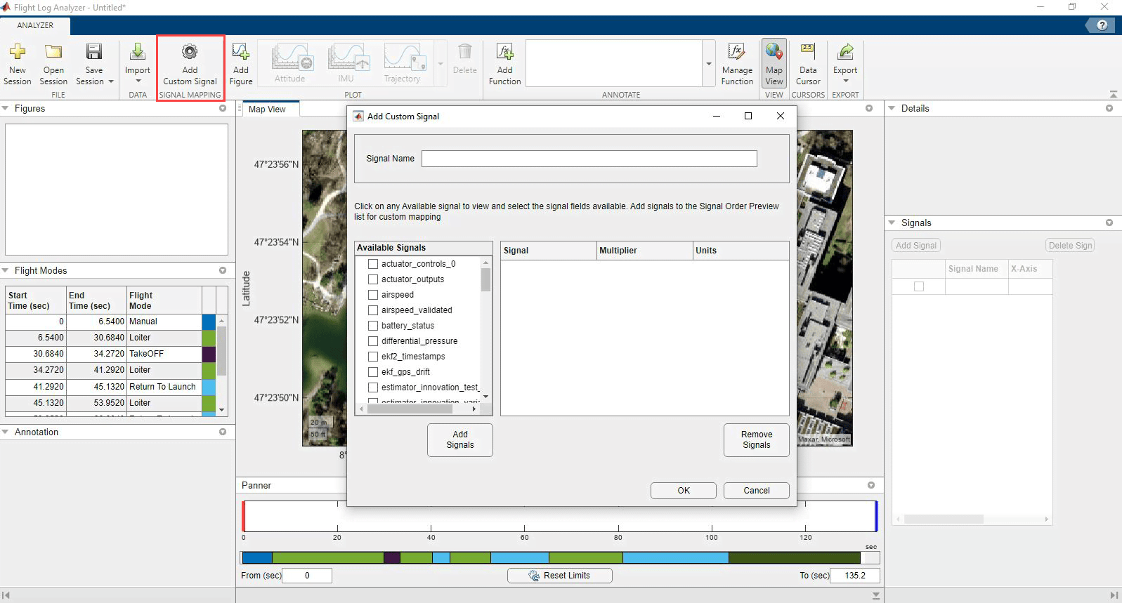
    Flight log analyzer app showing the Add Custom Signal dialog box

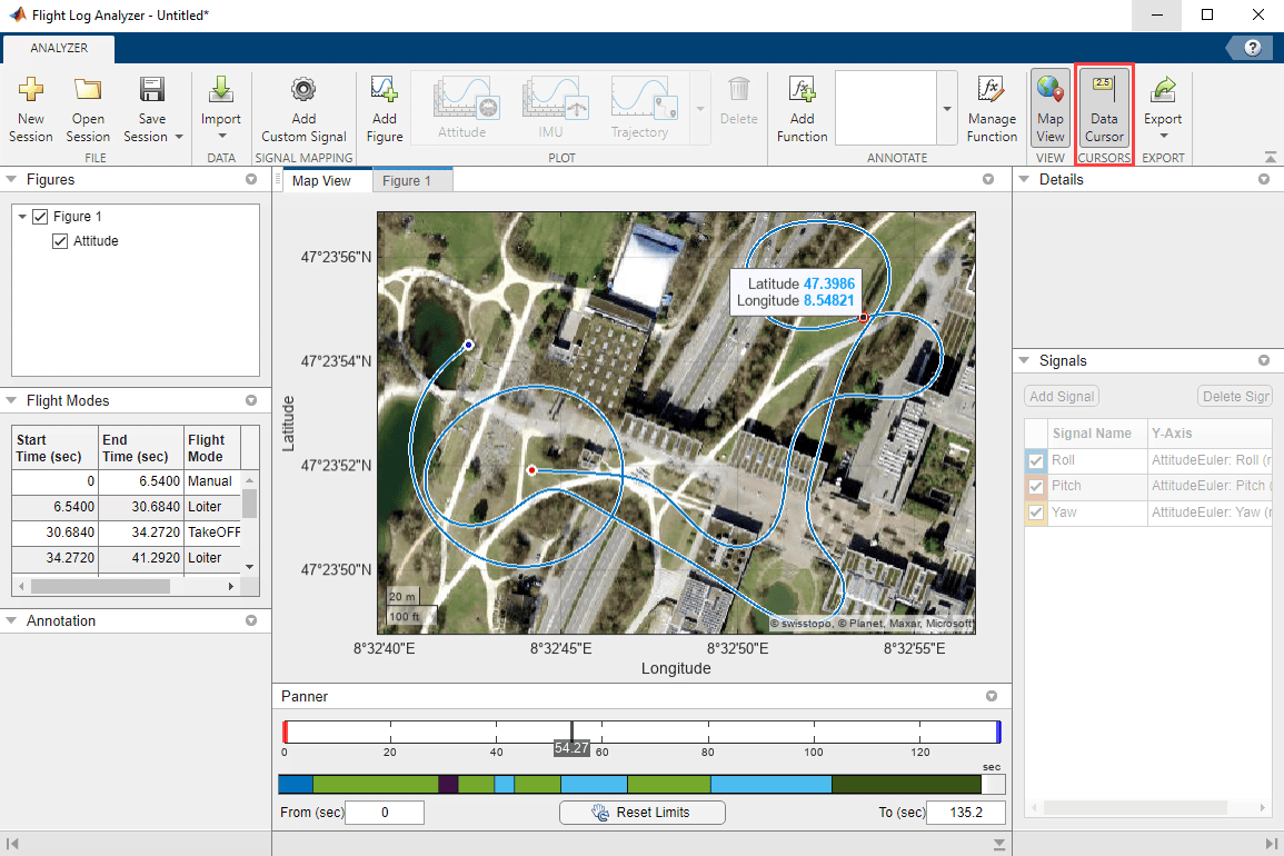
  • You can now explore plot data interactively using the Data Cursor. In the app toolstrip, select Data Cursor to add a handle to the Panner, that you can drag, and data tips to the plot, which are small text boxes that display information about individual data points. You can use the data cursor with Timeseries plots, and on Map View.
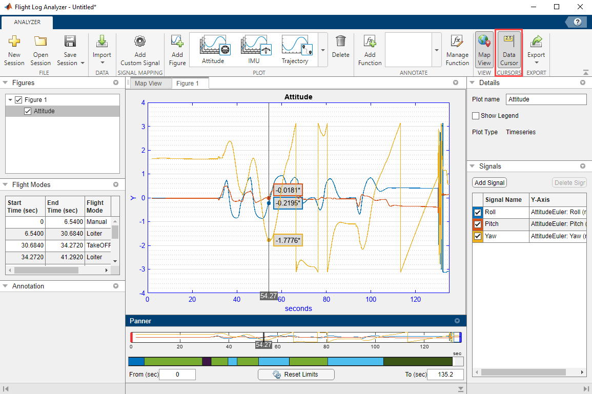
    Flight log analyzer app showing the Data Cursor on a timeseries plot

    Flight log analyzer app showing the Data Cursor in Map view

R2022b

New Features, Bug Fixes, Compatibility Considerations

Spatial Math: Use SE(2), SE(3), SO(2), and SO(3) transformations

Use the se3 and so3 objects to represent 3-D transformation matrices and 3-D rotation matrices, respectively. These objects make it easier to perform common operations, such as transforming 3-D points, normalizing the rotation, or interpolating between positions and orientations. To represent multiple transformations and rotations, you can arrange these objects into arbitrarily shaped arrays.

The se2 and so2 objects represent 2-D transformation matrices and 2-D rotation matrices, respectively.

Use plotTransforms to visualize the transformations and rotations in a figure. This can be helpful to see the underlying positions and orientations and to see interpolation results.

UAV Mission: Design and import UAV missions

Use the uavMission object to design or import UAV missions for multirotor and fixed-wing UAVs. Import UAV missions from plan files (.plan) or waypoint files (.waypoints) and add mission actions using object functions such as addTakeoff and addWaypoint. Use the fixedwingMissionParser and multirotorMissionParser mission parser objects to generate flight trajectories as fixedwingFlightTrajectory and multirotorFlightTrajectory objects, respectively. For more information, see Simulate UAV Mission in Urban Environment.
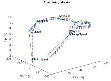
Fixed-wing UAV mission

Obstacle Avoidance: Avoid obstacles using 3D vector field histogram

Use the controllerVFH3D System object to compute an obstacle-free direction for a UAV using the sensor-data-based positions of obstacles, the UAV position, the UAV orientation, and a target position. Use the show function to visualize the sensor readings and cost matrix, which can help you tune the parameters of your algorithm. For more information, see Tune 3D Vector Field Histogram Controller for Obstacle Avoidance in 3D Scene.

Flight Log Analyzer: Flight Log Analyzer app enhancements

The Flight Log Analyzer app has been updated with these enhancements:

  • The Flight Log Analyzer app now supports custom annotations. Custom annotation enables you to write custom functions to label plots with region of interest (ROI) and point labels. The Function Gallery shows all of the custom functions you add. You can use the Annotation pane to interact with the labels and display them on the plots. You can export the annotations and signals to workspace as labeledSignalSet objects.

  • Improved filtering of the ulogreader object, the mavlinktlog object, and a flightLogSignalMapping object with custom log data from other variables when importing them from the workspace.

  • The Signal Browser pane now opens as a window when you double-click the data field of the desired signal in the Signals pane.

  • The Left and Right boxes in the Panner pane have been renamed to From (sec) and To (sec), respectively. The boxes are now enabled only when a log file has been loaded into the app.

  • The Name box in the Details pane is now either Plot name or Figure name depending on the item selected in the Figures pane.

    • Plot name — Select a plot item in the Figures pane.

    • Figure name — Select a figure item in the Figures pane.
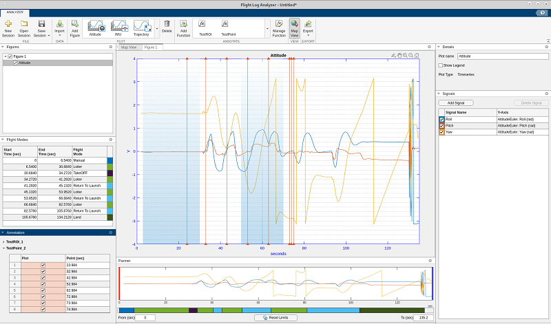
Flight log analyzer 22b update

OSM Import Enhancement: UAV scenario OSM import verbose mode

The addMesh function of the uavScenario object now supports verbose OSM import using a name-value argument. Specify Verbose as true to print or store import information, such as the total number of imported buildings.

scene = uavScenario(ReferenceLocation=[40.707088 -74.012146 0]);
addMesh(scene,"terrain",{"gmted2010",[-1000 1000],[-1000 1000]},[0.6 0.6 0.6])
addMesh(scene,"buildings",{"manhattan.osm",[-800 800],[-800 800],"auto"},[0 1 0],Verbose=1)
show3D(scene);
Importing C:\...\matlab\toolbox\shared\openstreetmapdata\manhattan.osm 
Latitude range (degree): [40.701 40.7182] 
Longitude range (degree): [-74.0188 -74.0003] 
Imported 657 out of 836 buildings
UAV Scenario Reference Latitude (degree): 40.7071 
UAV Scenario Reference Longitude (degree): -74.0121
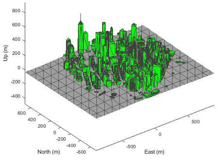
MATLAB figure of show function on Manhattan UAV scenario

Unreal Engine Scene: Added new suburban scene

The Suburban scene is an Unreal Engine® environment of a suburban area that contains houses with backyards, trees, power poles, and vehicles on the road.
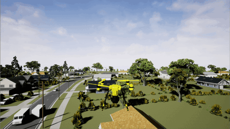
Suburban scene sample visualization.

Simulation 3D Scene Configuration: Use new MATLAB API to download maps locally from the server

Starting in R2022b, you can use the sim3d.maps class and its object functions to download prebuilt Unreal Engine scenes and access them directly from the Simulation 3D Scene Configuration block.

 Fisheye Camera Block Update: Fisheye camera block requires Computer Vision Toolbox and Image Processing Toolbox

Starting in R2022b, the Simulation 3D Fisheye Camera block requires Computer Vision Toolbox™ and Image Processing Toolbox™.

waypointTrajectory Reverse Motion: Specify wait and reverse motion for waypoint trajectory

You can now specify wait and reverse motion using the waypointTrajectory System object.

  • To let the trajectory wait at a specific waypoint, simply repeat the waypoint coordinate in two consecutive rows when specifying the Waypoints property.

  • To render reverse motion, separate positive (forward) and negative (backward) groundspeed values by a zero value in the GroundSpeed property.

PX4 Support Package Updates

R2022a

New Features, Bug Fixes, Compatibility Considerations

UAV Scenario Designer: Design and visualize UAV simulation scenarios interactively

Interactively design and visualize UAV Scenarios for path planning and control algorithms using the UAV Scenario Designer. Import terrain, pick and place simple and complex geometries to create a complex scene. Add multiple drones to the scenario and assign trajectories. Visualize drone moving through scenario. Place sensors on your UAV and simulate the scenario before exporting to MATLAB or Simulink.

UAV Scenario Designer app

Simulation 3D Lidar Reflectivity: Model surface reflections in Unreal Engine environment

In the Simulation 3D Lidar block, use the Reflectivity output port to output the reflectivity of surface materials in the Unreal Engine environment.

OpenCV Radial Distortion in Simulation 3D Camera Block: Simulate cameras with OpenCV supported radial distortion model in Unreal Engine Environment

In the Simulation 3D Camera block, you can now use the OpenCV six-coefficient formula for modeling radial distortion. Specify the formula to the Radial distortion coefficients parameter. This is in addition to the two-coefficient and three-coefficient models already supported by camera calibration tools in Computer Vision Toolbox. For more information on calibrating a camera using the six-coefficient formula, see Camera Calibration and 3D Reconstruction in the OpenCV documentation.

Simulation 3D Camera Performance Improvements: Run cameras at improved speeds during Unreal Engine simulation

The Simulation 3D Camera block now has improved simulation performance and runs at higher frame rates. This table shows the increase in frames per second (FPS) for each camera in an Unreal Engine simulation.

Number of Cameras in SimulationFrame Rate per Camera (R2021b)Frame Rate per Camera (R2022a)Percent Improvement per Camera
175.85 FPS88.45 FPS16.6%
430.51 FPS32.80 FPS7.5%

These simulations were timed on a Windows 10, Intel® Xeon W-2133 CPU @ 3.60 GHz, with 64 GB of RAM and a GPU with 8 GB of on-board RAM.

These improvements enable you to run cameras at real-time speeds, provided that your system meets the requirements specified by the Unreal Engine Simulation Environment Requirements and Limitations.

 Simulation 3D Environment Upgrade: Run 3D simulations using Unreal Engine 4.26

The 3D visualization engine that comes installed with UAV Toolbox has been updated to Unreal Engine 4.26. Previously, the toolbox used Unreal Engine 4.25.

For information about using Unreal Engine to create custom scenes, see Customize Unreal Engine Scenes for UAVs and Unreal Engine Simulation Environment Requirements and Limitations.

 Compatibility Considerations

If your Simulink model uses an Unreal Engine executable or project developed using a prior release of the UAV Toolbox Interface for Unreal Engine Projects support package, the simulation may return an error. To migrate the project so that it is compatible with the R2022a version of the support package, see Migrate Projects Developed Using Prior Support Packages.

Trajectory Generation: Create minimum jerk and minimum snap polynomial trajectories with Simulink

Use the Minimum Jerk Polynomial Trajectory block to generate multi-axis, minimum jerk, polynomial trajectories.

Use the Minimum Snap Polynomial Trajectory block to generate multi-axis, minimum snap, polynomial trajectories.

Import buildings from OSM files

The addMesh function now accepts "buildings" as an argument to import buildings from an OSM file as a mesh.

MAVLink 3p upgrade in UAV Toolbox

The MAVLink message definitions (dialects) and MAVLink serialization helper functions in UAV Toolbox now obtain their message definitions and serialization functions from the mavlink/message_definitions/v1.0/ and mavlink/c_library_v2 versions of the repositories, respectively.

PX4 Support Package Updates

R2021b

New Features, Compatibility Considerations

Simulate UAV Scenarios Using Simulink

You can now use UAV scenarios to simulate systems and advance the simulation using Simulink blocks:

GPS Sensor Block

Use the GPS block to simulate a GPS sensor with noise-corrupted measurements based on the input position and velocity. The block uses the WGS84 earth model to convert local coordinates to latitude-longitude-altitude (LLA) coordinates. You can vary the horizontal position, vertical position, and velocity accuracies to change noise levels in the output signals. Also, you can specify a decay factor, which models global position noise.

INS Sensor Block

Use the INS block to model and simulate an INS sensor and generate INS measurements in Simulink.

Video Streaming to UAV Hardware

The Video Send block sends a UDP video stream to a network address. Send images as a video feed to a hardware board, such as the NVIDIA Jetson™, or other compatible GStreamer clients. You can send images captured by sensors in an Unreal scenario for hardware-in-the-loop (HIL) simulation.

Fixed-Wing UAV Point Mass Block

The Fixed-Wing UAV Point Mass block integrates the fourth- or sixth-order fixed-wing point mass equations of motion in coordinated flight.

Obstacle Avoidance Block

Use the Obstacle Avoidance block to compute an obstacle-free direction using range sensor data and a target position.

Minimum Jerk and Snap Polynomial Trajectories

Use the minjerkpolytraj function to generate a minimum jerk polynomial trajectory. Specify waypoints, time points, and number of samples to get a series of jerks, accelerations, velocities, and positions.

Use the minsnappolytraj function to generate a minimum snap polynomial trajectory. Specify waypoints, time points, and number of samples to get a series of snaps, jerks, accelerations, velocities, and positions.

Flight Log Analyzer App Enhancements

The Flight Log Analyzer app has been updated with these enhancements:

  • The flight modes in the Flight Modes pane are now interactive. You can select one or more consecutive flight modes. The Panner limits values and adjusts handles accordingly.

  • The Signals pane now displays the units of the signals.

  • The axes labels of the plots are now customizable.

  • You can now export multiple plots to a single figure or separate figures.

 Simulation 3D Environment Upgrade: Run 3D simulations using Unreal Engine, Version 4.25

The 3D visualization engine that comes installed with UAV Toolbox has been updated to Unreal Engine, Version 4.25. Previously, the toolbox used Unreal Engine, Version 4.23.

For information about using Unreal Engine to create custom scenes, see Customize Unreal Engine Scenes for UAVs.

 Compatibility Considerations

If your Simulink model uses an Unreal Engine executable or project developed using a prior release of the UAV Toolbox Interface for Unreal Engine Projects support package, the simulation might produce an error. To migrate the project so that it is compatible with the R2021b version of the support package, see Migrate Projects Developed Using Prior Support Packages.

Simulation 3D Environment Performance Improvements: Run 3D simulations faster than real-time

Simulink co-simulations with Unreal Engine can run faster than real-time. Previously, the Unreal Engine frames-per-second (FPS) was limited by the inverse of the simulation sample rate. If you want to slow down a 3D simulation to investigate the system behavior, you can still use simulation pacing.

To control simulation time, use the Simulation 3D Scene Configuration block parameter Sample time. For example, if Sample time is 1/30, then the visualization engine solver tries to achieve a minimum frame rate of 30 fps. However, the real-time graphics frame rate is often lower due to factors such as graphics card performance and model complexity. With reasonable graphics card performance and less model complexity, the fps could be greater than 30, not limited to 30 as it was in previous releases.

Position Adjustments of Unreal Engine Cameras: Update relative translation and rotation of camera sensors during simulation

In the Simulation 3D Camera and Simulation 3D Fisheye Camera blocks, use the Translation and Rotation input ports to update the position of the cameras relative to their mounting positions during simulation. You can use these position adjustments to better model actuator dynamics, isolation mounting, and calibration workflows.

Previously, you could set only constant relative positions by using the Relative translation [X, Y, Z] (m) and Relative rotation [Roll, Pitch, Yaw] (deg) parameters. Now, by selecting Input to enable the corresponding ports, the parameters specify the initial position and the ports specify the position during simulation.

Unreal Engine Vehicle Enhancements: Import custom meshes

You can configure the Simulation 3D UAV Vehicle block to import custom meshes using this process:

  1. Install the UAV Toolbox Interface for Unreal Engine Projects support package. See Install Support Package for Customizing Scenes.

  2. On the block Parameters tab, set Type to Custom.

  3. In the Path to custom mesh field, enter the path to the vehicle mesh in the Unreal Engine project. To create a custom vehicle mesh, see Prepare Custom UAV Vehicle Mesh for the Unreal Editor.

  4. Use the vehicle dimensions in the custom mesh to enter the dimensions in the corresponding block parameter fields.