Simulate Safe Landing of UAV in Unexplored Environment Using Unreal Engine
This example shows how to simulate the safe landing operation of an Unmanned Aerial Vehicle (UAV) in an unexplored environment.
To safely operate in an unexplored environment, a UAV needs to have an autonomous safe landing capability. If the UAV detects a critical anomaly such as abnormalities in the battery or navigation system, the UAV must be able to scan the environment, determine a safe landing zone, and safely land without hitting any obstacle. To scan the environment, the UAV uses a lidar sensor data to create a map of the unexplored environment, and determine the safe landing area.
The safe landing operation consists of the following operation modes which are implemented in a Stateflow® chart that is integrated with a Simulink® model.
Mission Mode — UAV flies on the flight path specified by the mission waypoints.
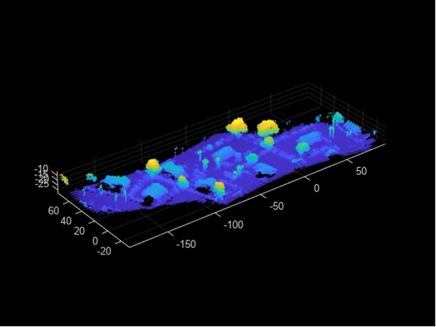
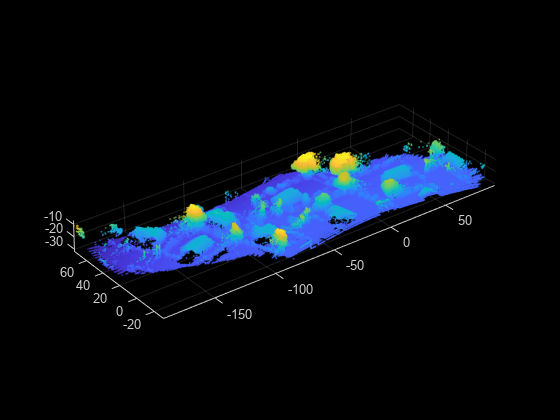
Emergency Mode — UAV creates a map of the environment from the point cloud data gathered from the lidar sensor.
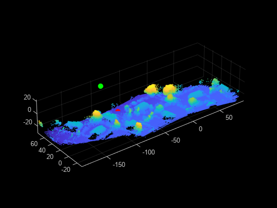
Hover and Detect Mode — UAV hovers and uses the map to find a safe landing zone.
Land Mode — Once a safe landing zone is determined, the UAV lands.
Follow these steps to simulate safe landing operation.
Specify the UAV mission waypoints in the Simulink® model.
Interface the Simulink model with the Suburban scene.
Add a UAV with a lidar sensor.
Specify the time of the emergency.
Run the Simulink model.
Prerequisites
This example visualizes the safe landing operation in 3D environment using Unreal Engine®. For more information on requirements and limitations of this simulation environment, visit Unreal Engine Simulation Environment Requirements and Limitations.
Model Overview
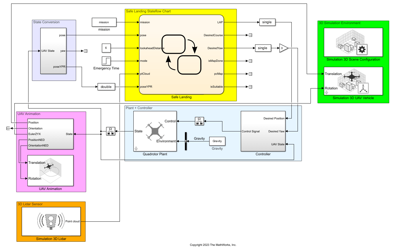
uavSafeLanding.slx consists of the following subsystems.
Safe Landing Stateflow Chart — Implements the different operation modes of the safe landing operation using a Stateflow chart.
3D Simulation Environment — Renders the 3D simulation environment using Unreal Engine.
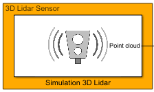
3D Lidar Sensor — Simulates a lidar sensor in a 3D simulation environment rendered using Unreal Engine.
Plant + Controller — Simulates the UAV plant model and position controller.
Open the Simulink model.
open_system("uavSafeLanding.slx") Specify the mission waypoints in the NED frame.
mission = [41 15.3 0; 41 15.3 -50; 100 -100 -50; 100 -100 0];
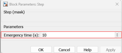
Set the time in seconds in which emergency mode is triggered by specifying the Emergency time (s) parameter in the Emergency Time block.
Safe Landing Stateflow Chart
This example represents each of the safe landing operation modes using a Stateflow chart state.
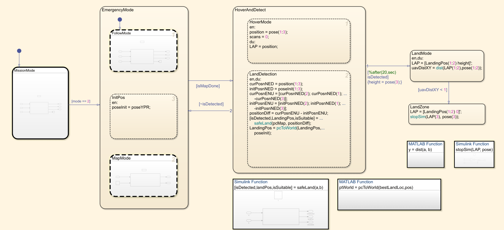
The chart consists of the following states:
MissionMode — Represents the Mission Mode state. In this state, the UAV flies on the flight path specified by the mission waypoints from take-off until the emergency mode is triggered. The UAV uses the Waypoint Follower block to compute the desired pose for the controller subsystem based on the current pose, lookahead distance, and the specified mission waypoints.
EmergencyMode — Represents the Emergency Mode state. Emergency mode (
mode == 2) triggers at the time specified by the Emergency time (s) parameter. In this mode, the UAV uses the lidar sensor to gather point cloud data and build a map of the unexplored environment. After completely building the map, the mode setsisMapDonetotrue, and the UAV transitions to the Hover and Detect mode.
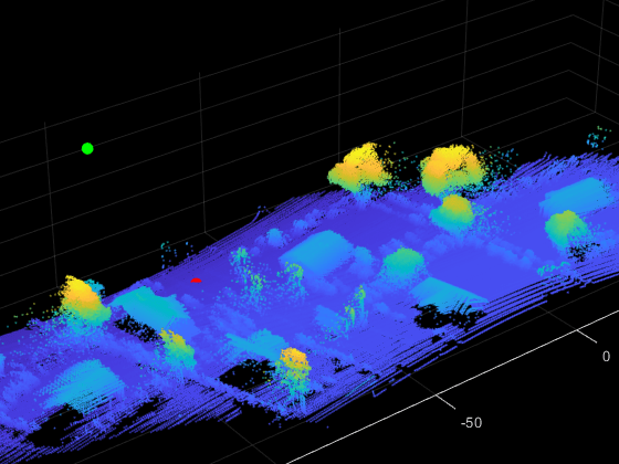
HoverAndDetect — Represents the Hover and Detect mode state. In this state, the UAV hovers and uses the generated map to determine a safe landing area. For more information, see the Determine Safe Landing Area for Aerial Vehicles (Lidar Toolbox) example. Once the UAV determines a safe landing area, the mode sets
isDetectedtotrueand triggers the Land Mode. The map shows the UAV (green dot) and the safe landing zone (red dot).
LandMode — Represents the Land Mode state. In this state, the UAV moves horizontally to hover above the landing area. After reaching the landing area, the UAV descends vertically to land.
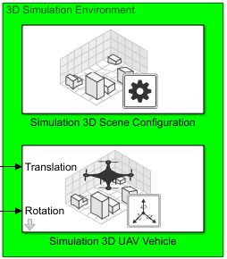
3D Simulation Environment
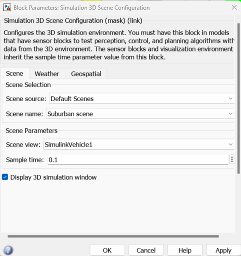
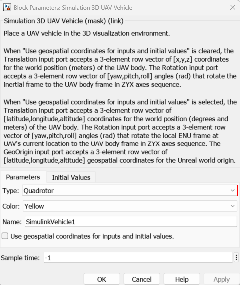
This subsystem configures the scene and UAV in an Unreal Engine environment. Download the Suburban scene from the sim3d.maps.Map.Server and configure the Simulation 3D Scene Configuration block. Select the quadrotor vehicle in the Simulation 3D UAV Vehicle block. For more details on configuring this subsystem, see Simulate Simple Flight Scenario and Sensor in Unreal Engine Environment example.
sim3d.maps.Map.server;
        MapName                        Description                    Version
    ________________    __________________________________________    _______

    "Suburban scene"    "a suburban area beyond the city's border"      "1"
sim3d.maps.Map.download("Suburban scene");Map is successfully downloaded and is up-to-date
sim3d.maps.Map.local;
        MapName                        Description                    Version
    ________________    __________________________________________    _______

    "Suburban scene"    "a suburban area beyond the city's border"      "1"
set_param("uavSafeLanding","SimulationCommand","update");
set_param("uavSafeLanding/Simulation 3D Scene Configuration","SceneDesc","Suburban scene");
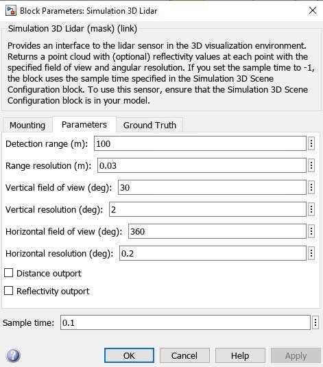
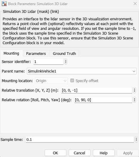
3D Lidar Sensor
Use the Simulation 3D Lidar block to mount the lidar sensor to the UAV. Set the parameters to model the Velodyne VLP-16 lidar sensor that is commonly used in aerial applications. Note that the lidar sensor has a relative pitch rotation of 90 deg, which enables the sensor to scan the ground.
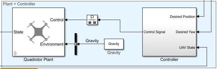
Plant and Controller
The Plant + Controller subsystem consists of a quadrotor plant model and the controller. The quadrotor plant represents a reduced-order multirotor UAV model using the Guidance Model block, which estimates the UAV state based on the control and environmental inputs. The controller consists of an outer PID position controller and an inner attitude PID controller. The controller computes the roll, pitch, yaw, and thrust control commands from the desired position, desired yaw, and UAV state.
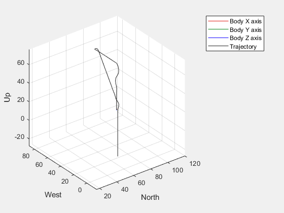
Simulate Safe Landing of UAV
Start the simulation. The UAV takes off from the first waypoint and moves to the subsequent waypoints. When the UAV initiates Emergency mode, it computes a safe landing zone and lands.
sim("uavSafeLanding.slx")Warning: Method 'getInstance' is not defined for class 'CloneDetector.ExclusionEditorUIService' or is removed from MATLAB's search path.
ans =
  Simulink.SimulationOutput:

                logsout: [1x1 Simulink.SimulationData.Dataset]
                   tout: [191701x1 double]

     SimulationMetadata: [1x1 Simulink.SimulationMetadata]
           ErrorMessage: [0x0 char]
Conclusion
This example demonstrates the implementation of a safe landing operation for a multirotor UAV. A map of an unexplored environment in Unreal Engine is constructed using lidar sensor data, and a safe landing area is determined. This example also shows how you can implement the different modes of the safe landing operation using Stateflow.