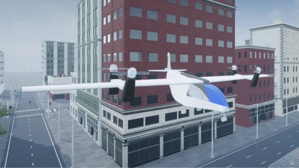
Visualize VTOL UAV Takeoff and Forward Transition
This example shows how to visualize a VTOL UAV aircraft during vertical takeoff and forward transition in Unreal Engine®.
Prerequisites
To run this example, you must install the UAV Toolbox Interface for Unreal Engine® Projects and download the 3D model of the VTOL UAV.
1. For more information on how to download and install the UAV Toolbox Interface for Unreal Engine® Projects, see Install Support Package for Customizing Scenes. This process installs the Unreal Engine plugins and the AutoVrtlEnv project.
2. Run this code to download the 3D model of the VTOL UAV from the MathWorks® website. The Design and Tune Controller for VTOL UAV reference application also uses this 3D model.
zipFile = matlab.internal.examples.downloadSupportFile("uav","data/VTOLAsset.zip");
filepath = fileparts(zipFile);
dataFolder = fullfile(filepath,"VTOLAsset");
unzip(zipFile,dataFolder)
Model Overview
Open the VTOLUAVTakeoffModel.slx Simulink® model.
modelName = "VTOLUAVTakeoffModel";
open_system(modelName)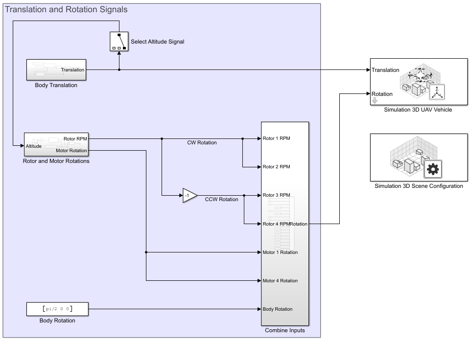
The model consists of these blocks and subsystems:
Simulation 3D Scene Configuration
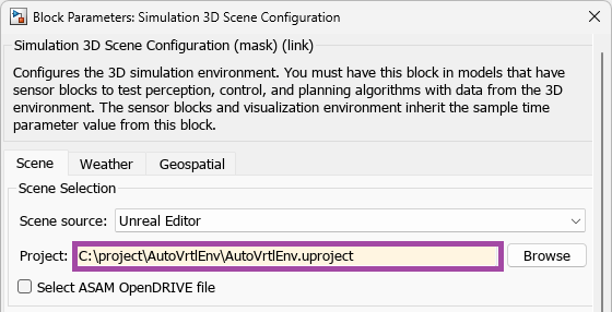
The Simulation 3D Scene Configuration block enables you to simulate the VTOL UAV mission in a 3D environment using Unreal Engine.
To configure this block for this example, specify the Project parameter of the Simulation 3D Scene Configuration block as the path to the AutoVrtlEnv project on your system. Then, in the block mask, click Open Unreal Editor and import the VTOL UAV model into Unreal Editor.
For more information on how to import the VTOL UAV model into Unreal Editor, see the Import VTOL Vehicle into Unreal Engine section of the Visualize VTOL UAV Mission over Urban Environment example.
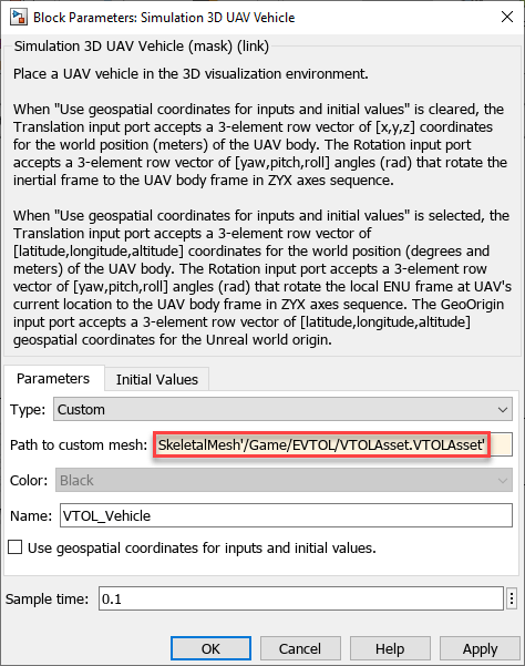
Simulation 3D UAV Vehicle
The Simulation 3D UAV Vehicle block places the VTOL UAV model in the 3D scene.
To configure this block for this example, specify the Type parameter as Custom. Then, copy the reference to the VTOL UAV asset from Unreal Editor by right-clicking the VTOLAsset and selecting Copy Reference.
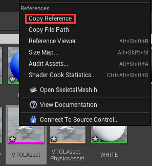
Paste the reference path into the Path to custom mesh parameter, and select OK.
Simulation 3D Custom UAV Pack
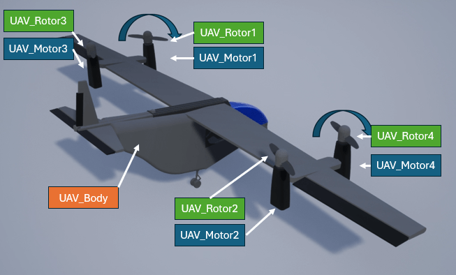
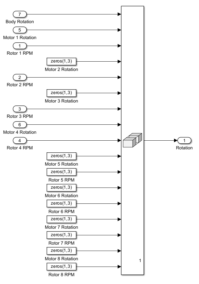
This model uses the Simulation 3D Custom UAV Pack block to generate the translation and rotation inputs for the Simulation 3D UAV Vehicle block. The block is configured to accept the body translation, body rotation, tilt angles for motors 1 and 4, and angular velocities of rotors 1 to 4.
![]()
The VTOL UAV mesh is configured with the bone hierarchy that is shown in the following image. For more details on how to configure custom UAV mesh for simulation in Unreal Engine, visit Prepare Custom UAV Vehicle Mesh for Unreal Engine Scenario Simulation.
Body Translation
The Body Translation subsystem outputs the body translation vector for the body translation input of the Simulation 3D Custom UAV Pack block. This subsystem contains the UAV Body X Translation which outputs the X-axis component of the translation vector, and the UAV Body Altitude subsystem which outputs the Z-axis component of the translation vector. The Initial UAV Body Translation constant determines the position of the UAV at the start of the simulation.
In this example, the Body Translation subsystem is configured to output these X-, Y-, and Z- positions:
X-position — The UAV remains stationary on the X axis during the initial climb. After reaching 10 meters, the UAV starts to accelerate in the X direction at 2 meters per second squared.
Y-position — The UAV remains stationary on the Y axis during the entire simulation.
Z-position — The UAV initially starts at the ground, and takes off to a cruise altitude of 50 meters.
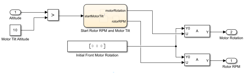
Rotor and Motor Rotations
The Rotor and Motor Rotations subsystem outputs the Motor Tilt and Rotor RPM signals for the Motor N Tilt and Rotor N RPM inputs of the Simulation 3D Custom UAV Pack block. This subsystem contains the Start Rotor RPM and Motor Tilt subsystem which starts motor tilt after the UAV has reached an altitude specified in the Motor Tilt Altitude constant.
In this example, the Rotor and Motor Rotations subsystem is configured to output these rotor RPM and motor tilt:
Rotor RPM — Rotors gradually increase in angular velocity to a maximum of 800 RPM.
Motor tilt — Motor tilt angle starts at 0 degrees (vertically upward). Starting at an altitude of 10 meters, tilt angle is gradually increased to a maximum of 90 degrees (horizontally forward).
Run Simulation
To run the simulation:
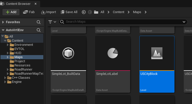
1. Open Unreal Editor. Navigate to Maps in the Content Browser and double-click USCityBlock to load the US City Block scene.
2. Open the Simulink model and click Run. After you click Run, Simulink model remains in the initialize state until you run the scene in Unreal Editor.
3. In Unreal Editor, click Play to run the scene.
![]()