Programmatically Build Simulink Models for CAN Communication
This example shows how to programmatically construct a Simulink® model to introduce CAN or CAN FD communication using a CAN DBC file. With the add_block (Simulink) and set_param (Simulink) functions of Simulink, one can add and fully configure Vehicle Network Toolbox™ blocks to add network communication to a basic algorithm. The DBC file contains the CAN messages and signal details. The primary focus is to programmatically configure CAN and CAN FD Pack and Unpack block parameters. This can significantly increase model construction efficiency.
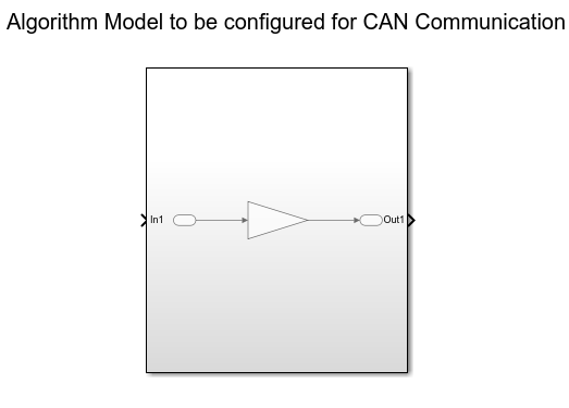
Algorithm Model
The example model AlgorithmModel.slx contains a subsystem block called "Algorithm". This block represents any given application algorithm developed in Simulink. A Gain (Simulink) block with value of 2 is inside this subsystem for demonstration purposes. This subsystem has a CAN signal input named "In1". This input value is scaled by the gain value. The scaled value is given as the output of this subsystem named "Out1". For experimentation, the gain value can be changed and the Gain block can be replaced by a different algorithm.
CAN Database File Access
You can access the contents of CAN DBC files with the canDatabase function. Through this function, details about network nodes, messages, and signals are available.
db = canDatabase("CANBus.dbc")db =
Database with properties:
Name: 'CANBus'
Path: 'C:\Users\jpyle\Documents\MATLAB\Examples\vnt-ex60686316\CANBus.dbc'
Nodes: {'ECU'}
NodeInfo: [1×1 struct]
Messages: {2×1 cell}
MessageInfo: [2×1 struct]
Attributes: {}
AttributeInfo: [0×0 struct]
UserData: []
A node "ECU" is defined in the example CAN DBC file as shown below.
node = nodeInfo(db,"ECU")node = struct with fields:
Name: 'ECU'
Comment: ''
Attributes: {}
AttributeInfo: [0×0 struct]
The node receives a CAN message "AlgInput" containing a signal "InitialValue". The signal "InitialValue" is the input to the algorithm.
messageInfo(db,"AlgInput")ans = struct with fields:
Name: 'AlgInput'
ProtocolMode: 'CAN'
Comment: ''
ID: 100
Extended: 0
J1939: []
Length: 1
DLC: 1
BRS: 0
Signals: {'InitialValue'}
SignalInfo: [1×1 struct]
TxNodes: {0×1 cell}
Attributes: {}
AttributeInfo: [0×0 struct]
The node transmits a CAN message "AlgOutput" containing a signal "ScaledValue". The signal "ScaledValue" is the output of the algorithm.
messageInfo(db,"AlgOutput")ans = struct with fields:
Name: 'AlgOutput'
ProtocolMode: 'CAN'
Comment: ''
ID: 200
Extended: 0
J1939: []
Length: 2
DLC: 2
BRS: 0
Signals: {'ScaledValue'}
SignalInfo: [1×1 struct]
TxNodes: {'ECU'}
Attributes: {}
AttributeInfo: [0×0 struct]
Programmatically Build the Model
Open the Example Model
Open the example model to be configured.
open AlgorithmModelAdd and Configure CAN Configuration Block
Add and position a CAN Configuration block in the model.
add_block("canlib/CAN Configuration","AlgorithmModel/CAN Configuration")
set_param("AlgorithmModel/CAN Configuration","position",[50,330,250,410])
Set the "Device" parameter to have the model use the MathWorks® virtual CAN device.
set_param("AlgorithmModel/CAN Configuration","Device","MathWorks Virtual 1 (Channel 1)")
Add and Configure CAN Receive Block
Add and position a CAN Receive block in the model.
add_block("canlib/CAN Receive","AlgorithmModel/CAN Receive")
set_param("AlgorithmModel/CAN Receive","position",[50,200,250,280])
Add a Terminator (Simulink) block and position it. This is used to connect the function port of the CAN Receive block. In this example, simple message reception is performed. In general, placing a CAN Receive inside a Function-Call Subsystem (Simulink) is the preferred approach to modeling with CAN blocks.
add_block("simulink/Sinks/Terminator","AlgorithmModel/Terminator")
set_param("AlgorithmModel/Terminator","position",[310,210,330,230])
Set the "Device" parameter to have the model use the MathWorks virtual CAN device.
set_param("AlgorithmModel/CAN Receive","Device","MathWorks Virtual 1 (Channel 1)")
Add and Configure CAN Unpack Block
Add and position a CAN Unpack block in the model. By default, the block is in "Raw Data" mode.
add_block("canlib/CAN Unpack","AlgorithmModel/CAN Unpack")
set_param("AlgorithmModel/CAN Unpack","position",[350,220,600,300])
Set the following parameters in the CAN Unpack block in a single function call:
DataFormat
CANdbFile
MsgList
set_param("AlgorithmModel/CAN Unpack","DataFormat","CANdb specified signals","CANdbFile",db.Path,"MsgList","AlgInput")
If the "DataFormat" and "CANdbFile" parameters are already set on a block, the chosen message is changeable by only including the "MsgList" parameter.
Add and Configure CAN Pack Block
Add and position a CAN Pack block in the model.
add_block("canlib/CAN Pack","AlgorithmModel/CAN Pack")
set_param("AlgorithmModel/CAN Pack","position",[1000,220,1250,300])
Set the following parameters in the CAN Pack block in a single function call:
DataFormat
CANdbFile
MsgList
set_param("AlgorithmModel/CAN Pack","DataFormat","CANdb specified signals","CANdbFile",db.Path,"MsgList","AlgOutput")
Add and Configure CAN Transmit Block
Add and position a CAN Transmit block in the model.
add_block("canlib/CAN Transmit","AlgorithmModel/CAN Transmit")
set_param("AlgorithmModel/CAN Transmit","position",[1350,220,1550,300])
Set the "Device" parameter to have the model use the MathWorks virtual CAN device. Also, periodic transmission is enabled with the default timing.
set_param("AlgorithmModel/CAN Transmit","Device","MathWorks Virtual 1 (Channel 1)")
set_param("AlgorithmModel/CAN Transmit", "EnablePeriodicTransmit", "on")
Make Connections Between the Blocks
The CAN blocks and the algorithm block added in the model must now be connected. The port co-ordinates for all CAN blocks are required.
canRxPort = get_param("AlgorithmModel/CAN Receive","PortConnectivity");
canUnpackPort = get_param("AlgorithmModel/CAN Unpack","PortConnectivity");
subSystemPort = get_param("AlgorithmModel/Subsystem","PortConnectivity");
canPackPort = get_param("AlgorithmModel/CAN Pack","PortConnectivity");
canTxPort = get_param("AlgorithmModel/CAN Transmit","PortConnectivity");
terminatorPort = get_param("AlgorithmModel/Terminator","PortConnectivity");

[canRxPortFunc,canRxPortMsg] = canRxPort.Position;
[canUnpackPortIn,canUnpackPortOut] = canUnpackPort.Position;
[subSystemPortIn,subSystemPortOut] = subSystemPort.Position;
[canPackPortIn,canPackPortOut] = canPackPort.Position;
canTxPortMsg = canTxPort.Position;
terminatorPortIn = terminatorPort.Position;
Add lines to connect all of the blocks in the appropriate order.
add_line("AlgorithmModel",[canRxPortMsg ; canUnpackPortIn])
add_line("AlgorithmModel",[canUnpackPortOut ; subSystemPortIn])
add_line("AlgorithmModel",[subSystemPortOut ; canPackPortIn])
add_line("AlgorithmModel",[canPackPortOut ; canTxPortMsg])
add_line("AlgorithmModel",[canRxPortFunc ; terminatorPortIn])
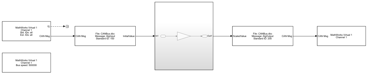
Completed Model
This is how the model looks after construction and configuration.
Test the Built Model
Configure a CAN Channel in MATLAB for Communication with the Algorithm Model
Create a CAN channel in MATLAB® using channel 2 of the MathWorks virtual CAN device. It will communicate with the CAN channel in the model. Also, attach the CAN database to the MATLAB channel to have it automatically decode incoming CAN data.
canCh = canChannel("MathWorks","Virtual 1",2);
canCh.Database = db;
For transmission from MATLAB to the model, use the CAN database to prepare a CAN message as input to the algorithm.
algInputMsg = canMessage(canCh.Database,"AlgInput");Run the Algorithm Model
Assign the simulation time and start the simulation
set_param("AlgorithmModel","StopTime","inf")
set_param("AlgorithmModel","SimulationCommand","start")
Pause until the simulation is fully started.
while strcmp(get_param("AlgorithmModel","SimulationStatus"),"stopped")
end
Run the MATLAB Code
Start the MATLAB CAN channel.
start(canCh);
Transmit multiple CAN messages with different signal data as input to the model.
for value = 1:5
    algInputMsg.Signals.InitialValue = value*value;
    transmit(canCh,algInputMsg)
    pause(1)
end
Receive all messages from the bus. Note the instances of the "AlgInput" and "AlgOutput" messages, their timing, and signal values.
msg = receive(canCh,Inf,"OutputFormat","timetable")
msg=10×8 timetable
    0.009728 sec    100    0     'AlgInput'         1    1    1×1 struct    0    0
     0.15737 sec    200    0    'AlgOutput'     [2,0]    2    1×1 struct    0    0
      1.0121 sec    100    0     'AlgInput'         4    1    1×1 struct    0    0
      1.1574 sec    200    0    'AlgOutput'     [8,0]    2    1×1 struct    0    0
      2.0146 sec    100    0     'AlgInput'         9    1    1×1 struct    0    0
      2.1574 sec    200    0    'AlgOutput'    [18,0]    2    1×1 struct    0    0
      3.0177 sec    100    0     'AlgInput'        16    1    1×1 struct    0    0
      3.1574 sec    200    0    'AlgOutput'    [32,0]    2    1×1 struct    0    0
      4.0219 sec    100    0     'AlgInput'        25    1    1×1 struct    0    0
      4.1574 sec    200    0    'AlgOutput'    [50,0]    2    1×1 struct    0    0
The canSignalTimetable function provides an efficient way to separate and organize the signal values of CAN messages into individual timetables for each.
signalTimeTable = canSignalTimetable(msg)
signalTimeTable = struct with fields:
     AlgInput: [5×1 timetable]
    AlgOutput: [5×1 timetable]
signalTimeTable.AlgInput
ans=5×1 timetable
    0.009728 sec     1
      1.0121 sec     4
      2.0146 sec     9
      3.0177 sec    16
      4.0219 sec    25
signalTimeTable.AlgOutput
ans=5×1 timetable
    0.15737 sec     2
     1.1574 sec     8
     2.1574 sec    18
     3.1574 sec    32
     4.1574 sec    50
Stop the CAN channel.
stop(canCh)
Stop the Algorithm Model
set_param("AlgorithmModel","SimulationCommand","stop")
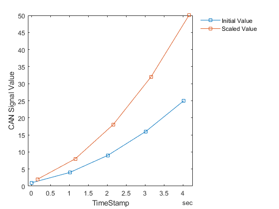
Plot the Signal Data
Plot the initial and scaled signal values of the CAN messages against the timestamps as they occurred on the virtual bus. Note the change in values as transmitted by MATLAB and the scaling of the data as performed by the model.
plot(signalTimeTable.AlgInput.Time,signalTimeTable.AlgInput.InitialValue,"Marker","square","MarkerIndices",1:5)
hold on
plot(signalTimeTable.AlgOutput.Time,signalTimeTable.AlgOutput.ScaledValue,"Marker","square","MarkerIndices",1:5)
hold off
xlabel("TimeStamp");
ylabel("CAN Signal Value");
legend("Initial Value","Scaled Value","Location","northeastoutside");
legend("boxoff");