LTE Turbo Decoder
Decode turbo-encoded samples
Libraries:
Wireless HDL Toolbox /
Error Detection and Correction
Description
The LTE Turbo Decoder block implements the turbo decoder required by
LTE standard TS 36.212 [1] and provides an
interface and architecture optimized for HDL code generation and hardware deployment.
The block iterates over two MAX decoders. You can specify the number of iterations. The
coding rate is 1/3. The block accepts encoded bits as a 3-by-1 vector of soft-coded
values, [S P1 P2]. In this vector, S is the
systematic bit, and P1 and P2 are the parity bits
from the two encoders.
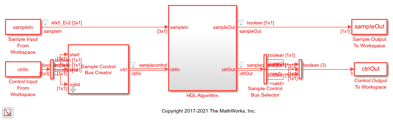
This block uses a
streaming sample interface with a bus for related control signals. This interface enables the
block to operate independently of frame size, and to connect easily with other Wireless HDL Toolbox™ blocks. The block accepts and returns a value representing a single sample, and a
bus containing three control signals. These signals indicate the validity of each sample and the
boundaries of the frame. To convert a matrix into a sample stream and these control signals, use
the Frame To Samples block
or the whdlFramesToSamples
function. For a full description of the interface, see Streaming Sample Interface.
The block can accept the next frame only after it has completed decoding the previous
frame. You must leave
Iterations*2*HalfIterationLatency+BlockSize+4
idle cycles between input frames. The half-iteration latency is described in the Algorithms section.
Alternatively, you can use the output signal
ctrl.end to determine when the block is
ready for new input.
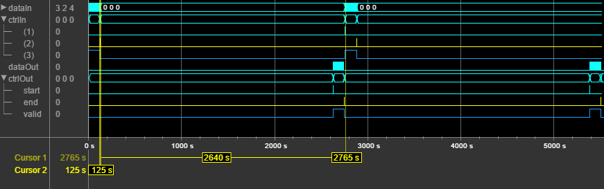
This waveform shows an input frame of 120 samples (+ 4 tail bits), and 2632 idle
cycles between frames. Each input sample is a vector of three fixed-point soft-decision
values. The input and output ctrl buses are expanded to show the
control signals. start and end show the frame
boundaries, and valid qualifies the data samples.
Examples
Turbo Decode Streaming Samples
Use LTE Turbo Decoder block to decode data, and how to compare hardware-friendly design with results from LTE Toolbox™.
Ports
Input
Output
Parameters
Algorithms
The block implements an iterative decode algorithm using a single decoder and single interleaver. This diagram shows the conceptual algorithm for one iteration.
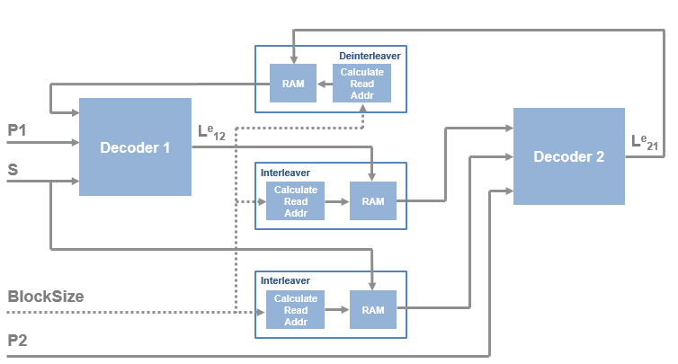
Although the diagram shows two decoders and three interleavers, the block actually implements the algorithm using only one decoder and one interleaver. The decoder performs one half-iteration and interleaves the results. Then the output is routed back to the input for the next half-iteration. The interleaver computes the interleave indexes from the block size. For details of the interleaver implementation, see LTE Turbo Encoder.
The odd half-iterations compute the likelihood ratio from uninterleaved bits (P1, S, and deinterleaved results of P2 decoding). The even half-iterations compute the likelihood ratio from the interleaved bits (P2 and interleaved results of P1 and S decoding).
The decoder block uses the BCJR algorithm to find the likelihood ratio of a particular bit [2].
The probabilities can also be represented in terms of current and future states:
The α probability represents the previous state, β represents the current state
probability, and ɣ represents the next state. The algorithm calculates ɣ from the input
values. The α and β probabilities are calculated using forward and backward recursion
over the possible states of the trellis, and also depend on ɣ. All calculations are done
in the log domain.
The initial conditions for α and β are:
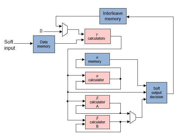
This diagram shows the half-iteration decoder and interleaver architecture. The initial likelihood is set to zero.
In a normal BCJR architecture, the algorithm cannot compute β until the entire frame
is in memory. It must perform a full-frame forward trace and then a full-frame backward
trace, which means the latency of one half-iteration is two frame lengths. The required
memory is
BlockSize*NumStates*DataWidth.
In this case, NumStates is eight, from LTE standard TS 36.212 [1].
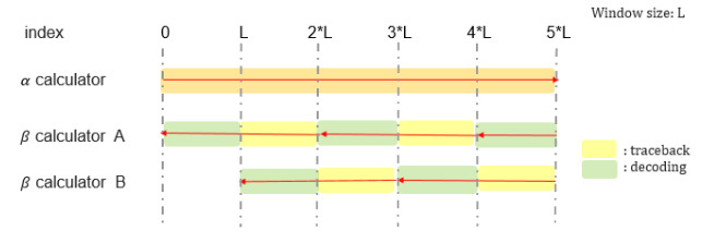
However, this decoder implementation uses a sliding window to reduce the required memory and the latency of the algorithm [3]. The window size is 32 samples, which is five times the trellis constraint length of 7. The latency of one half-iteration is:
The required memory with sliding window is 2*32*NumStates*DataWidth. This figure shows how the β calculation traces and decodes one window at a time, alternating input between the A and B calculation blocks.
References
[1] 3GPP TS 36.212. "Multiplexing and channel coding." 3rd Generation Partnership Project; Technical Specification Group Radio Access Network; Evolved Universal Terrestrial Radio Access (E-UTRA). URL: https://www.3gpp.org.
[2] Bahl, L. R., J. Cocke, F. Jelinek, and J. Raviv. "Optimal Decoding of Linear Codes for Minimizing Symbol Error Rate." IEEE Transactions on Information Theory. Vol 1T-20, March 1974, pp. 284–287.
[3] Viterbi, Andrew J. "An Intuitive Justification and a Simplified Implementation of the MAP Decoder for Convolutional Codes." IEEE Journal on Selected Areas in Communications. Vol. 16, No. 2, February 1998.
Extended Capabilities
Version History
Introduced in R2017b