
- 2.4K (All time)
- 27 (Last 30 days)
- 4.7 / 5
- Community
-
25 Jun 2020

Boost Converter with Analog PI Controller
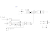
Boost Converter with Analog PI Controller (Used only Op Amp & 555 Timer)
Boost Converter with Analog PI Controller. The PI controller used +-5V supply to work. It does not requires any digital controller. It only need five operational amplifiers and one 555 timer to work
- 829 (All time)
- 8 (Last 30 days)
- 5.0 / 5
- Community
-
14 May 2018

Speed control of DC motor with PI controller
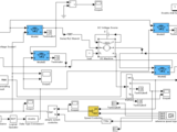
Speed controller of DC motor with API controller from modelling of DC motor
Speed controller of DC motor with API controller from modelling of DC motor
- 1.6K (All time)
- 17 (Last 30 days)
- 5.0 / 5
- Community
-
14 Jan 2021

Raspberry Pi IO Control Utility
Test or Control Raspberry Pi IO pins with this Matlab GUI
Setup the Raspberry Pi to work with Matlab. Check out the Matlab Hardware Support Package documentation. This GUI based program will automatically connect to the Raspberry Pi if already configured
- 2.7K (All time)
- 3 (Last 30 days)
- 5.0 / 5
- Community
-
29 Apr 2018

PI-controller for inverted pendulum
animated, with derivation in jpg-image
http://simulations.narod.ru/It is inverted pendulum. Down point is base can be controlled. It can be moved horizontally only. PI (not PID) controller used to set the pendulum in up direction. There
- 1.2K (All time)
- 2 (Last 30 days)
- 5.0 / 5
- Community
-
26 Nov 2011

DSFOC drive and Kessler's criteria
Simple yet effective and practical PI controller analytical tuning in the DSFOC drive.
The modulus [magnitude] and symmetric[al] optimum criteria (the Kessler's variants) are used to tune the PI current and speed controllers in a direct stator field-oriented controller (DSFOC) for
- 1K (All time)
- 2 (Last 30 days)
- 5.0 / 5
- Community
-
27 Aug 2015
PI Control of Three-phase Voltage Source PWM Rectifier
Current loop controller, voltage loop controller
- 1.1K (All time)
- 13 (Last 30 days)
- 5.0 / 5
- Community
-
13 May 2022

This is a model of BOOST CONVERTER. spl. feature is o/p voltage controlled using this controller.
have done there is no such need in order to produce a pulse,which will be automatically generated by PID controller.Even the inductor current if you observe you will observe exact continous current mode
- 5.6K (All time)
- 3 (Last 30 days)
- 5.0 / 5
- Community
-
14 Jun 2013

Adaptive fuzzy PI controller for V/F control method of three phase induction motor
This model represents the improved V/F control method using adaptive fuzzy PI controller.
An adaptive fuzzy PI controller (AFPIC) with V/F control method of 3 phase induction motor is presented, where the PI parameters are adjusted by fuzzy due to changing the operating conditions.
- 2.7K (All time)
- 6 (Last 30 days)
- 4.8 / 5
- Community
-
8 Oct 2016
Optimization of PI controller of a dc motor four quadrant speed control through ICA
optimization of PI controler of DCmotor speed control by Imperialist competitive algorithm
the range of the optimization of the parameters by changing [varmin] and [varmax] matrix in the 'Main_ImperialistCompetitveAlgorithm.m' file.After you got the optimized value of PI parameters just put
- 1.7K (All time)
- 4 (Last 30 days)
- 5.0 / 5
- Community
-
14 May 2012

Boost Converter PI Control Demo
This Simulink model demonstrate DC-DC Boost Converter with simple PI Feedback Control
This Simulink model demonstrate DC-DC Boost Converter with simplePI Feedback Control to boost 5V DC to 12V DC at switching frequency of 10kHz
- 1.7K (All time)
- 17 (Last 30 days)
- 5.0 / 5
- Community
-
23 Apr 2019

Buck Converter PI Control Demo
This Simulink model demonstrate DC-DC Buck Converter with simple PI Feedback Control
This Simulink model demonstrate DC-DC Buck Converter with simplePI Feedback Control to buck 12V DC to 5V DC at switching frequency of 10kHz
- 2K (All time)
- 10 (Last 30 days)
- 5.0 / 5
- Community
-
8 Jun 2019
(V/F) Control of Induction Motor using Fuzzy-Tuned PI
(V/F) Control of Induction Motor using Fuzzy-Tuned PI Controller
The term "Voltage/Frequency (V/F) Control of Induction Motor using Fuzzy-Tuned PI Controller" refers to a method of regulating the operation of an induction motor by adjusting both its voltage and
- 612 (All time)
- 4 (Last 30 days)
- 5.0 / 5
- Community
-
11 Aug 2023
Simulink Toolbox for the Modeling and Analysis of Thermodynamic Systems, such as gas turbines
- 4.3K (All time)
- 22 (Last 30 days)
- 4.5 / 5
- Community
-
24 May 2024

CAN device driver mcp2515 for Arduino and Raspberry Pi
This blocks provide CAN communication feature using CAN Controller device MCP2515 via SPI.
CAN device driver mcp2515 has the Controller Area Network(CAN) communicated feature via SPI communication.This library blocks are modeled for mcp2515 using SPI blocks.You can use this blocks both
- 2.3K (All time)
- 7 (Last 30 days)
- 4.9 / 5
- Community
-
25 Oct 2017

Active and reactive power control for a three-phase inverter
Decoupled active and reactive power control for a three-phase inverter connected to the utility grid based on the PI controller.
controller (i.e., outer loop), and then the output of the PI regulator represents the reference direct axis current of the inverter which is regulated by the inner PI controller. The same procedure could be
- 3.9K (All time)
- 46 (Last 30 days)
- 5.0 / 5
- Community
-
15 Jan 2021
PSO tuned PI controller for speed control of the BLDC motor with variable inertia.
DOP-capable PSO is used to tune the PI speed controller for the BLDC motor with variable inertia.
This file contains an implementation of DOP-capable PSO used to adapt controller gains in a situation of sudden inertia change of the motor. The .pro file contains an implementation for PLC
- 3.2K (All time)
- 6 (Last 30 days)
- 4.5 / 5
- Community
-
4 Oct 2015
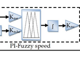
Controlling of D.C. Motor using PI and PI-Fuzzy Logic Controller
Controlling of D.C. Motor using PI and PI-Fuzzy Logic Controller
Controlling of D.C. Motor using PI and PI-Fuzzy Logic Controller
- 2.7K (All time)
- 8 (Last 30 days)
- 4.3 / 5
- Community
-
11 Nov 2017

Three phase rectifier closed loop voltage controller RL load
Three phase rectifier closed loop voltage controller R-L load using PI controller
Three phase rectifier closed loop voltage controller R-L load using PI controller
- 646 (All time)
- 7 (Last 30 days)
- 5.0 / 5
- Community
-
14 Jan 2021

CUK CONVERTER WITH PI CONTROLLER
This model helps you in getting a basic idea of a CUK converter and PI application in converter.
noticed from this model is that,it has a PI controller,which can be used for giving a DC constant(desired value of DC o/p),and the error signal is sent through a PI controller,which further helps in setting
- 2.7K (All time)
- 1 (Last 30 days)
- 4.2 / 5
- Community
-
7 Jun 2013

LOAD FREQUENCY CONTROL MATLAB/Simulink - With & Without PI Controller - Freq Deviation Step Response
LOAD FREQUENCY CONTROL IN MATLAB/SIMULINK
- 2.6K (All time)
- 8 (Last 30 days)
- 4.6 / 5
- Community
-
5 Mar 2018

Simulation of Closed loop boost converter using Discrete PI Controller
Simulation of Closed loop boost converter using Discrete PI ControllerOutput voltage required -> 240 volts Step by step design of controller https://youtu.be/58JlCZfm_Yw
- 2K (All time)
- 18 (Last 30 days)
- 5.0 / 5
- Community
-
25 Oct 2020
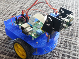
Control a Raspberry Pi powered robot with MATLAB and Simulink
Control a Raspberry Pi powered robot with MATLAB and Simulink
This project shows you how to control a Raspberry Pi powered robot from both MATLAB and Simulink.Take basic control of your robot from MATLAB and prototype an image processing technique for target
- 3.2K (All time)
- 4 (Last 30 days)
- 4.2 / 5
- Community
-
21 Apr 2016
BLDC motor control using PI controller
This model considers the speed control of a brush-less DC motor using a proportional-integral (PI) controller.
- 10.1K (All time)
- 16 (Last 30 days)
- 4.4 / 5
- Community
-
4 Nov 2014
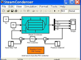
Steam Condenser Model and PI Control
A dynamic model of a steam condenser with PID control.
- 5.8K (All time)
- 3 (Last 30 days)
- 4.5 / 5
- Community
-
12 Feb 2008

Control Raspberry Pi from your Android Device using Simulink
Control Raspberry Pi from your Android Device using Simulink
These files offer resources on how to create and run a Simulink model on Raspberry Pi to build a surveillance camera with wireless communication capabilities. It also highlights how you can use
- 1.3K (All time)
- 2 (Last 30 days)
- 5.0 / 5
- Community
-
1 Nov 2016

Boost converter with pi controller
Boost converter output is controlled by pi controller
To step up the dc voltage boost converter is used.in this model the output voltage is controlled by PI controller.
- 8.4K (All time)
- 5 (Last 30 days)
- 3.7 / 5
- Community
-
18 Jul 2013

PV System with optimization algorithms
The Simulink model based on PV system (consisting of PV, Battery, Converter, PI Controller, inverter, and charge controller
In this Project we design the Simulink model based on PV system (consisting of PV, Battery, Converter, PI Controller, inverter, and charge control) architecture. Next we deploy the MPPT Controller
- 8.4K (All time)
- 23 (Last 30 days)
- 4.8 / 5
- Community
-
6 Dec 2019

PID Control: Description, Examples, and Tuning
Use and tune a PID (Proportional, Integral, Derivative) Controller for your project
PID controllers are popular and effective in many systems. i explain how to implement and tune a PID controller through concrete examples of MATLAB controlling a VEX EDR Robot through a wireless
- 1.1K (All time)
- 6 (Last 30 days)
- 5.0 / 5
- Community
-
12 Jul 2017

Configurable Simulink Model for DC-DC Converters with PWM PI Control
A Simulink model configurable to buck, boost and buck-boost DC-DC converters with PWM PI control
This package includes a configurable Simulink model for three different types of DC-DC converters (Buck, Boost and Buck-Boost converters) with a PWM PI controller. The example provided shows a case
- 46.5K (All time)
- 23 (Last 30 days)
- 4.2 / 5
- Community
-
1 Apr 2009
Non-ideal Buck Converter Transfer Function
The closed loop system design using PI controller for non-ideal buck converter
- 448 (All time)
- 2 (Last 30 days)
- 5.0 / 5
- Community
-
6 Feb 2018

Speed and position controllers tuning using PSO
Speed and position controllers for a DC/BLDC drive are tuned simultaneously using PSO.
- 2.8K (All time)
- 5 (Last 30 days)
- 5.0 / 5
- Community
-
16 Oct 2015

DC-to-DC Step-down Buck Converter. PI Controlled
DC-to-DC Step-down Buck Converter and short report containing stress test information is included.
discussed. As it can be seen from the results of the experiments, controller fulfill given tasks and shows good results for given specifications. In addition, controller and the circuit is able to perform
- 2K (All time)
- 6 (Last 30 days)
- 4.2 / 5
- Community
-
23 Nov 2014
Z-source converter with single phase inverter fed motor and has voltage control using PI controller
In MATLAB/Simulink the Z-Source converter does the boost operation and the full bridge inverter converts into AC voltage. The voltage control have been done in closed loop control using PI
- 1.1K (All time)
- 3 (Last 30 days)
- 5.0 / 5
- Community
-
23 Aug 2016
- 6.7K (All time)
- 2 (Last 30 days)
- 4.3 / 5
- Community
-
17 Nov 2005
Two area load frequency control using pi cintroller
Two area lfc
- 1.2K (All time)
- 3 (Last 30 days)
- 4.5 / 5
- Community
-
5 Apr 2017
Vector Control of Permanent Magnet Synchronous Motor (PMSM)
This file simulates the SVPWM control of a typical PMSM drive using PI controllers.
This file simulates the SVPWM control of a typical PMSM drive using PI controllers.
- 5.9K (All time)
- 28 (Last 30 days)
- 4.0 / 5
- Community
-
22 Jul 2017
LINKIG PSO CODE WITH THE SIMULINK MODEL
This file shows how can link your PSO code with Matlab Simulink to determine the parameters of the PI controller.
This file shows how can link your PSO code with Matlab Simulink to determine the parameter of the PI controller. Also, SSR is damped using TCSC, and the constant power control is used to generates
- 1.3K (All time)
- 6 (Last 30 days)
- 5.0 / 5
- Community
-
25 Jul 2019
Rotor system PI+D controler with Arduino and Simulink
In this project are shown how to control a SISO system with arduino and simulink
This project shown a way to calibrate PI+D gains, by controlling a beam system. This project use Arduino, MATLAB, Simulink, and the real time functions implemented in simulink platform. this project
- 623 (All time)
- 3 (Last 30 days)
- 4.0 / 5
- Community
-
21 Jul 2016

The PI controller with anti windup (clamping) is implemented using code.
When the PI controller is implemented into hardware, the conventional PI controller or the Integrator block in Simulink cannot be used. This code represent these block in the form of code so that it
- 671 (All time)
- 1 (Last 30 days)
- -- / 5
- Community
-
3 Mar 2020

Electrohydraulic Servoactuator with PI Controller
Simulation of Electrohydraulic Servoactuator with PI Controller
mathematical modeling of the Electrohydraulic servoactuator and steps of design of the PI controller are given in my book:M Galal Rabie, Fluid Power Engineering, McGraw-Hill, NY, May 18, 2009, pp 340-350 and
- 890 (All time)
- 1 (Last 30 days)
- -- / 5
- Community
-
1 Nov 2010

PI Controller for Electrohydraulic Servoactuator
Improvement of dynamic behavior of electrohydraulic servoactator by implementing a PI controller
mathematical modeling of the Electrohydraulic servoactuator and steps of design of the PI controller are given in my book:M Galal Rabie, Fluid Power Engineering, McGraw-Hill, NY, May 18, 2009, pp 340-350 and
- 1.4K (All time)
- 1 (Last 30 days)
- -- / 5
- Community
-
24 Jul 2009

Two area load freq control using PI controller
two area load freq control using PI controller
two area load freq control using pi controller
- 73 (All time)
- 2 (Last 30 days)
- -- / 5
- Community
-
7 Feb 2022

This demonstrates the advantage of PR controller over PI controller for controlling periodic parameter.
This block implements a continuous Proportional Resonant controller using transfer function kr*s / s^2+(2*pi*f)^2It allows user to set the proportional gain (kp), resonant gain (kr) and resonant
- 1.5K (All time)
- 32 (Last 30 days)
- -- / 5
- Community
-
21 Oct 2022
Using Fuzzy Logic Controller the gain of PI controller was Adjusted
Load Frequency Control of Three Area System using Fuzzy tunned PI Controller.
- 5.6K (All time)
- 3 (Last 30 days)
- 3.6 / 5
- Community
-
21 May 2011
How can i use the fuzzy logic control FLC instead of PI
In this model, the fuzzy logic control uses instead of PI controller to estimate the speed.
In this model, the fuzzy logic control FLC uses instead of PI controller to estimate the speed.
- 519 (All time)
- 2 (Last 30 days)
- 3.5 / 5
- Community
-
29 Jul 2019

FOMCON toolbox for MATLAB is dedicated to fractional-order modeling and control of dynamic systems.
- 21.5K (All time)
- 167 (Last 30 days)
- 4.6 / 5
- Community
-
25 Nov 2022
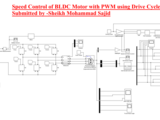
Speed Control of BLDC Motor using PWM with Drive Cycle
For PI Speed Control we need a Controlled Voltage Source but for PWM Speed Control we didn't need a Controlled Voltage Source
The BLDC motor can be controlled using a PI controller but we need a controlled voltage source for this. But using PWM speed controlled we didn't need a controlled voltage source [we can also use
- 2.5K (All time)
- 19 (Last 30 days)
- 5.0 / 5
- Community
-
14 Apr 2021
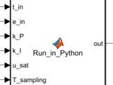
PI controller code in C and Python
A brief demonstration of the capability of Simulink to execute C/C++ and Python code as a part of the numerical model.
You've come to the right place if you wonder how to append your Simulink model with C/C++ and/or Python code. Exactly such a capability is demonstrated here. A code for the PI controller with
- 530 (All time)
- 1 (Last 30 days)
- -- / 5
- Community
-
29 Apr 2020

Closed loop of Boost converter with PI controller
Designing a closed-loop boost converter with a PI controller involves regulating the output voltage
Behavior of the Closed-Loop SystemLoad increases → output voltage tends to drop → PI increases duty cycle → inductor stores more energy → output voltage is restored.Input voltage drops → similar
- 119 (All time)
- 4 (Last 30 days)
- -- / 5
- Community
-
30 Apr 2025

Closed Loop PI Controller for Boost DC-DC Converter
Closed Loop PI Controller for Boost DC-DC Converter
Closed Loop PI Controller for Boost DC-DC Converter.Switching Frquency Fsw=5000Hz and Sampling Frequency Fs=100000 (both saved in Model Worksapce).Load Resistance R=20 Ohm & Vin=10Volt.L and C
- 1K (All time)
- 5 (Last 30 days)
- -- / 5
- Community
-
20 May 2021

Closed loop of buck converter with PI controller
A closed-loop Buck converter with a PI (Proportional-Integral) controller maintains a stable and accurate output voltage
losed-Loop Buck Converter: OverviewGoal: Regulate the output voltage VoutV_{out}Vout to match a reference voltage VrefV_{ref}Vref by adjusting the PWM duty cycle using a PI controller.Block Diagram
- 197 (All time)
- 20 (Last 30 days)
- -- / 5
- Community
-
30 Apr 2025

Optimization of PI controller of a dc motor four quadrant speed control through ICA
optimization using Imperialist competitive algorithm of PI controller of a dc motor speed control
this is the optimization of PI controller of dc motor speed control.this is done in matlab7.0.you can change the range of the PI controller for optimization,by changing [varmin],[varmax] matrix. in
- 1.4K (All time)
- 2 (Last 30 days)
- -- / 5
- Community
-
14 May 2012
Optimization of PI controller of a dc motor four quadrant speed control through ICA
application of ICA for optimization of PI controller of dc motor speed control
there is a 'Main_ImperialistCompetitveAlgorithm.m' file .just run it.there is two models.one is for final use after optimization.use the optimized PI parameter to thge final model.you can change the
- 1K (All time)
- 2 (Last 30 days)
- -- / 5
- Community
-
14 May 2012

Affordable and Portable DC Motor Laboratory Kit for Control Systems
Simulink Models to control a DC Motor with a Raspberry Pi.
University of Illinois at Urbana-Champaign. The models provided here are for a proportional and a proportional plus speed closed loop control of a DC motor. The kit includes a Raspberry Pi, an H-Bridge
- 665 (All time)
- 1 (Last 30 days)
- 5.0 / 5
- Community
-
14 Jun 2016

PI Controller for 1st & 2nd Order System in MATLAB Simulink
Simulate first and second-order systems with a PI controller using MATLAB Simulink. Observe improved control and steady-state accuracy.
PI Controller for 1st & 2nd Order System in MATLAB Simulink.This MATLAB Simulink project illustrates the simulation of first-order and second-order systems under the control of a
- 78 (All time)
- 8 (Last 30 days)
- -- / 5
- Community
-
10 May 2025
- 441 (All time)
- 2 (Last 30 days)
- -- / 5
- Community
-
28 Jun 2016

Simulation Of P,PI,PID controller
Matlab simulation of P, PI, and PID controllers with variable Transfer function/user-defined transfer function
Matlab simulation of P, PI, and PID controllers with variable Transfer function/user-defined transfer function ..here executed by Ziegler–Nichols method of tuning PID controller
- 419 (All time)
- 10 (Last 30 days)
- -- / 5
- Community
-
27 Dec 2022
Boost Circuit Using Supercapacitor with PI controller
This is a boost converter using supercap
boost converter using supercap and PI controller
- 698 (All time)
- 3 (Last 30 days)
- -- / 5
- Community
-
6 Jan 2017
Model File Package for Motor Control Design Public Video
Current Control PI Gain Tuning, Speed Closed Loop Control, Torque Control, Flux Weakening Control...
- 4.5K (All time)
- 19 (Last 30 days)
- 5.0 / 5
- Community
-
29 Jul 2019