By acquiring SiSoft and its products, MathWorks® is enabling you to go above and beyond your signal integrity analysis by integrating QCD and QSI workflows with MATLAB® and other products.
Signal Integrity Toolbox™ provides two apps: the Serial Link Designer app and Parallel Link Designer app, which offer the same pre-layout functionality and interfaces as QCD and QSI, respectively. You can use Signal Integrity Toolbox and RF PCB Toolbox™ for the post-layout capabilities of QCD and QSI. RF PCB Toolbox also provides full-wave electromagnetic techniques to analyze on-board interconnects. Both toolboxes will continue to grow in future product releases by incorporating the latest technologies and solutions for successful signal integrity designs.
Mapping Products
The pre-layout features and post-layout capabilities of QCD and QSI are now part of Signal Integrity Toolbox. You can still get the signal integrity analysis by using Signal Integrity Toolbox and RF PCB Toolbox. RF PCB Toolbox also provides full-wave electromagnetic techniques so you can analyze on-board interconnects such as vias and lossy transmission lines. You can use this analysis to obtain S-parameters, impedances, as well as charge and current distributions. If you use SimFarm for large scale simulation, you can now perform thousands of simulations using Parallel Computing Toolbox™ and scale those simulations to remote clusters with MATLAB Parallel Server™.
Introducing Signal Integrity Toolbox and RF PCB Toolbox
For pre-layout analysis, Signal Integrity Toolbox provides the Serial Link Designer app and Parallel Link Designer app. Both apps let you design and analyze high-speed serial and parallel links with the use of models such as IBIS-AMI and design kits for industry standards. These apps have the same interface as QCD and QSI.
You can use RF PCB Toolbox with Signal Integrity Toolbox for post-layout verification. RF PCB Toolbox lets you import PCB layouts into Signal Integrity Toolbox to correlate and validate your designs. Also, you can accurately predict impedance, loss, reflections, and crosstalk with RF PCB Toolbox.
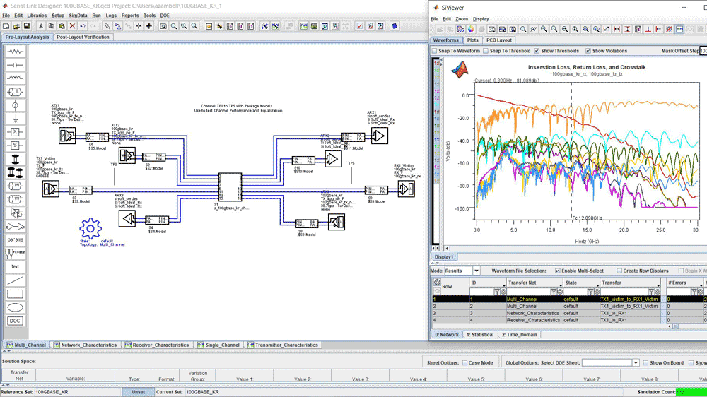
Design 100GBASE-KR serial link.
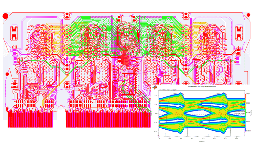
Verify post-layout performance of complex PCB.
Signal Integrity Capabilities
Signal Integrity Toolbox enables the complete workflow to analyze the signal integrity of high-speed links. For pre-layout analysis, you can describe analog channels using S-parameters, SPICE/IBIS models, and analytical models of lossy transmission lines and vias.
RF PCB Toolbox enables post-layout analysis and full-wave electromagnetic analysis of interconnect structures.
SerDes Toolbox™ lets you build dual IBIS-AMI models of transmitters and receivers, including equalization algorithms. You can analyze the end-to-end performance of your links with the Serial Link Designer app or Parallel Link Designer app and view your results in the Signal Integrity Viewer app.
RF Toolbox™ provides a rich set of functions to verify, manipulate, and visualize S-parameters for use in Signal Integrity Toolbox.
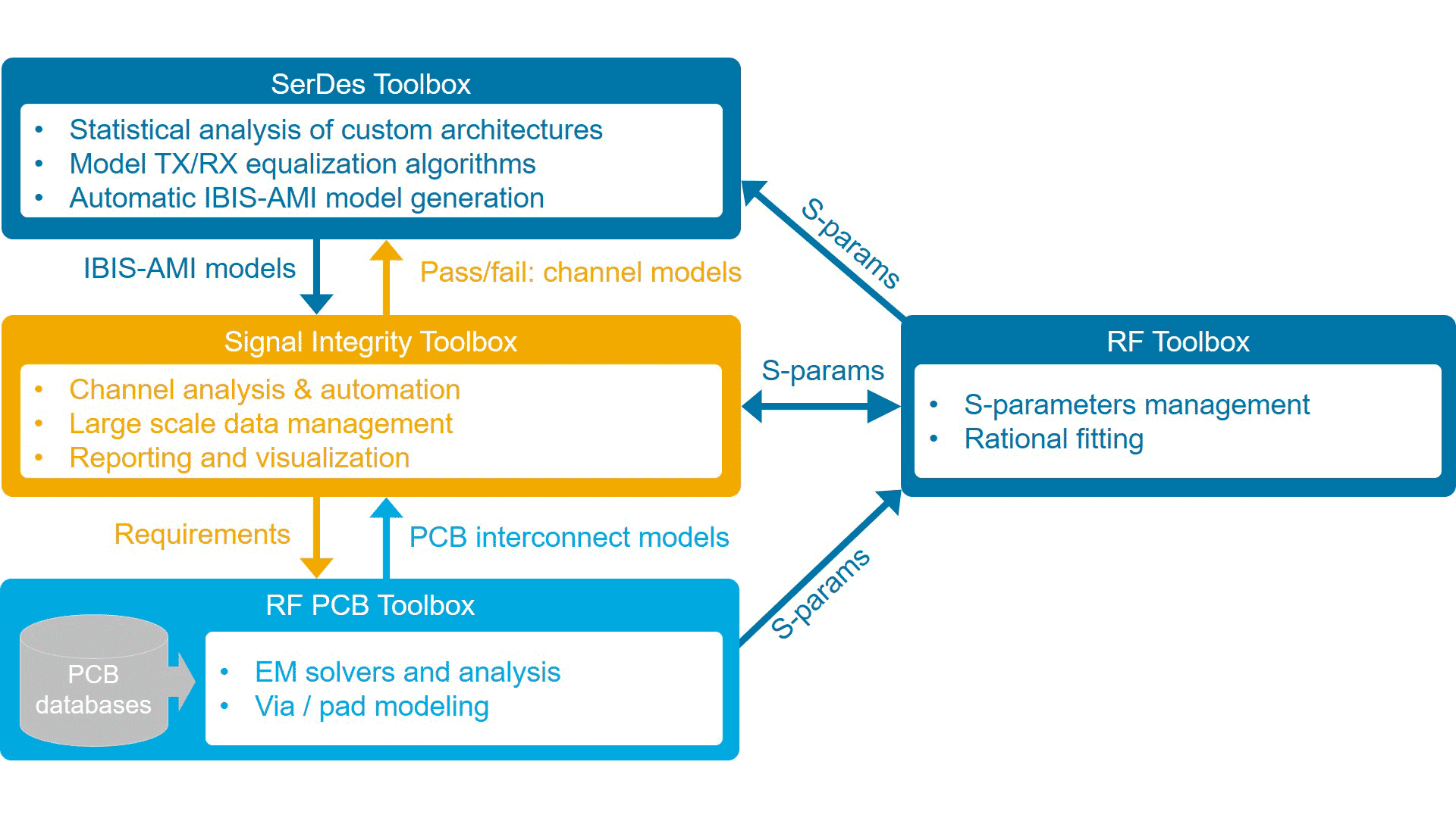
Interconnected workflow for SerDes design, pre-layout, and post-layout signal integrity analysis.