Configure AUTOSAR Internal Calibration Parameters
Note
For run-time calibration of AUTOSAR parameters and lookup tables, R2019a introduced graphical mapping of model workspace parameters to AUTOSAR component parameters. In the Code Mappings editor, you select a Simulink® model-workspace parameter, map it to an AUTOSAR component parameter, and modify its AUTOSAR calibration attributes. If you currently model AUTOSAR parameters or lookup tables by using AUTOSAR parameter objects in the base workspace, consider migrating to the Code Mappings editor workflow. For more information, see Map Model Workspace Parameters to AUTOSAR Component Parameters and Configure Lookup Tables for AUTOSAR Calibration and Measurement.
AUTOSAR internal calibration parameters are internal to an AUTOSAR software component,
and are accessed only by instances of the software component in which they are defined.
You can use AUTOSAR.Parameter data objects to configure internal
calibration parameters in Simulink. After creating and configuring the parameter data objects, you reference
them from block parameters in your model.
To configure AUTOSAR calibration parameters that can be accessed by other AUTOSAR software components, see Configure AUTOSAR Calibration Component.
To configure an AUTOSAR internal calibration parameter:
Set the value of a block parameter in your model to reference the name of the calibration parameter. For example, open the example model
autosar_swc_counter. Open the Model Data Editor (on the Modeling tab, click Model Data Editor) and select the Parameters tab. Change the value of the Constant block fromLIMITtomyPrm.Create an
AUTOSAR.Parameterdata object for the calibration parameter. While editing the parameter value in the Model Data Editor, click the action button next to
 myPrmand select Create.In the Create New Data dialog box, Value field, enter
AUTOSAR.Parameter.If you set Location to
Base
                                    Workspace
, you can set a storage class in theAUTOSAR.Parameterdialog box. To map a Simulink lookup table to the parameter, you use themapLookupTablefunction.If you set Location to
Model
                                    Workspace
, you cannot set a storage class in theAUTOSAR.Parameterdialog box. However, to map a Simulink lookup table to the parameter, you can use the Code Mappings editor, Parameters tab, or themapParameterfunction.
This example sets Location to
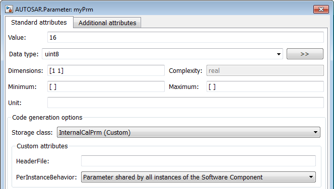
Base
                        Workspace
. Click Create. AnAUTOSAR.Parameterobject appears.In the
AUTOSAR.Parameterproperty dialog box, configure these properties:Value — Specify a value for the calibration parameter. For an internal calibration parameter, this value represents the initial value.
Data type — Specify a data type for the calibration parameter. For more information, see Specify Data Types Using Data Type Assistant.
Storage class — For a base workspace parameter, to specify an internal calibration parameter, from the drop-down list, select
InternalCalPrm. To specify Per instance behavior, select one of the following:Parameter shared by all instances of the Software ComponentEach instance of the Software Component has its own copy of the parameter
In the Configuration Parameters dialog box, in the Code Generation > Interface pane, clear the option Ignore custom storage classes, if it is not already cleared.
To map a Simulink lookup table to the base workspace AUTOSAR parameter
myPrm, use themapLookupTablefunction.Generate code.
Note
The software does not support the use of AUTOSAR calibration parameters within Model blocks.