Map AUTOSAR Elements for Code Generation
In Simulink®, you can use the Code Mappings editor and the AUTOSAR Dictionary separately or together to graphically configure an AUTOSAR software component and map Simulink model elements to AUTOSAR component elements. For more information, see AUTOSAR Component Configuration.
Use the Code Mappings editor to map Simulink model elements to AUTOSAR component elements from a Simulink model perspective. The editor display consists of several tabbed tables, including Functions, Inports, and Outports. Use the tables to select Simulink elements and map them to corresponding AUTOSAR elements. The mappings that you configure are reflected in generated AUTOSAR-compliant C code and exported ARXML descriptions.
The Code Mappings editor also provides mapping for submodels referenced from AUTOSAR software component models. For more information, see Map Calibration Data for Submodels Referenced from AUTOSAR Component Models.
Simulink to AUTOSAR Mapping Workflow
To map Simulink model elements to AUTOSAR software component elements:
Open a model for which AUTOSAR system target file
autosar.tlcis selected.Create or open a mapped view of the AUTOSAR model. In the model window, do one of the following:
From the Apps tab, open the AUTOSAR Component Designer app.
Click the perspective control in the lower-right corner and select Code.
If the model has not yet been mapped to an AUTOSAR software component, the AUTOSAR Component Quick Start opens. To configure the model for AUTOSAR component development, work through the quick-start procedure and click Finish. For more information, see Create Mapped AUTOSAR Component with Quick Start.
The model opens in the AUTOSAR Code perspective. This perspective displays the model and directly below the model, the Code Mappings editor.

The Code Mappings editor provides in-canvas access to AUTOSAR mapping information, with batch editing, element filtering, easy navigation to model elements and AUTOSAR properties, and model element traceability. To view and modify additional AUTOSAR attributes for an element, select the element and click the
 icon.
icon.Navigate the Code Mappings editor tabs to perform these actions:
Map a Simulink entry-point function to an AUTOSAR runnable.
Map a Simulink inport or outport to an AUTOSAR receiver or sender port and a sender-receiver data element, with a specific data access mode.
Map a Simulink model workspace parameter to an AUTOSAR component parameter.
Map a Simulink data store to an AUTOSAR variable.
Map a Simulink block signal or state to an AUTOSAR variable.
Map a Simulink data transfer line to an AUTOSAR inter-runnable variable (IRV).
Map a Simulink function caller to an AUTOSAR client port and a client-server operation.
Use the Filter contents field (where available) to selectively display some elements, while omitting others, in the current view.
After mapping model elements, click the Validate button
 to validate the AUTOSAR component
configuration. If errors are reported, address them and then retry
validation.
to validate the AUTOSAR component
configuration. If errors are reported, address them and then retry
validation.
Map Entry-Point Functions to AUTOSAR Runnables
The Functions tab of the Code Mappings editor supports modeling AUTOSAR runnable entities (runnables) in Simulink. After using the AUTOSAR Dictionary to create AUTOSAR runnables and AUTOSAR events, which implement aspects of internal behavior in an AUTOSAR component, open the Code Mappings editor. Use the Functions tab to map Simulink entry-point functions to AUTOSAR runnables.
For more information, see Configure AUTOSAR Runnables and Events.
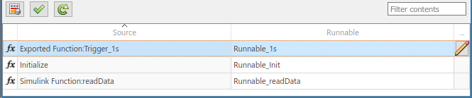
The Functions tab of the Code Mappings editor maps each
Simulink entry-point function to an AUTOSAR runnable. Click the
Update button ![]() to load or update Simulink entry-point functions in the model.
to load or update Simulink entry-point functions in the model.
In the Functions tab, you can:
Map a Simulink entry-point function by selecting the entry-point function and then selecting a menu value for an AUTOSAR runnable, among those listed for the AUTOSAR component.
Specify software address methods (
SwAddrMethods) for the runnable function code and internal data. If you specifySwAddrMethodnames, code generation uses the names to group runnable function and data definitions in memory sections. For more information, see Configure SwAddrMethod.The
SwAddrMethodnames must be defined in the model. For example, the example modelautosar_swc_counterdefinesSwAddrMethods named CODE and VAR.To specify
SwAddrMethods for a runnable, select the corresponding entry-point function and click the icon. The dialog displays the code
attributes SwAddrMethod and Internal Data
SwAddrMethod for the selected function. Select
SwAddrMethodnames among the valid values listed for each property.For runnables that contain Stateflow® charts, the execution functions generated by the Stateflow charts inherit
SwAddrMethods from their parent runnable. (since R2023b)To create additional
SwAddrMethodnames in the component, use the AUTOSAR Dictionary, SwAddrMethods view. For more information, see Configure AUTOSAR SwAddrMethods.
Note
Code generation for runnable internal data SwAddrMethods
requires setting the model configuration option Code Generation > Interface > Generate separate internal data per entry-point
function (GroupInternalDataByFunction) to
on.
Map Inports and Outports to AUTOSAR Sender-Receiver Ports and Data Elements
The Inports and Outports tabs of the Code Mappings editor support modeling AUTOSAR sender-receiver (S-R) communication in Simulink. After using the AUTOSAR Dictionary to create AUTOSAR S-R ports, S-R interfaces, and S-R data elements in your model, open the Code Mappings editor. Use the Inports and Outports tabs to map Simulink root inports and outports to AUTOSAR receiver and sender ports and AUTOSAR S-R data elements.
For more information, see Configure AUTOSAR Sender-Receiver Communication and Configure AUTOSAR Queued Sender-Receiver Communication.
The Inports tab of the Code Mappings editor maps each Simulink root inport to an AUTOSAR receiver port and an S-R interface data element. In the Inports tab, you can:
Map a Simulink inport by selecting the inport and then selecting menu values for an AUTOSAR port and an AUTOSAR element, among those listed for the AUTOSAR component.
Select an AUTOSAR data access mode for the port:
ImplicitReceive,ExplicitReceive,ExplicitReceiveByVal,QueuedExplicitReceive,ErrorStatus,IsUpdated,EndToEndRead, orModeReceive.

To view additional port communication specification (ComSpec) attributes, select
an inport and click the ![]() icon.
icon.
For AUTOSAR non-queued receiver ports, you can modify ComSpec attributes
AliveTimeout,HandleNeverReceived, andInitValue.For queued receiver ports, you can modify ComSpec attribute
QueueLength.
For more information, see Configure AUTOSAR Sender-Receiver Port Communication Specification Attributes.
The Outports tab of the Code Mappings editor maps each Simulink root outport to an AUTOSAR sender port and an S-R interface data element. In the Outports tab, you can:
Map a Simulink outport by selecting the outport and then selecting menu values for an AUTOSAR port and an AUTOSAR element.
Select an AUTOSAR data access mode for the port:
ImplicitSend,ImplicitSendByRef,ExplicitSend,QueuedExplicitSend,EndToEndWrite, orModeSend.
Note
Models configured for the AUTOSAR Classic Platform do not support multi-dimensional arrays for outports mapped with data access mode ImplicitSendByRef.
To view additional port communication specification (ComSpec) attributes, select
an outport that maps to an AUTOSAR non-queued sender port and click the ![]() icon. In the dialog, you can modify the ComSpec
attribute
icon. In the dialog, you can modify the ComSpec
attribute InitValue. For more information, see Configure AUTOSAR Sender-Receiver Port Communication Specification Attributes.
Map Model Workspace Parameters to AUTOSAR Component Parameters
On the Parameters tab of the Code Mappings editor, you can map Simulink model workspace parameters to AUTOSAR parameters for AUTOSAR run-time calibration. Examples of model workspace parameters you can map include:
Simulink parameter objects
Simulink lookup table objects
Simulink breakpoint objects
By mapping lookup table and breakpoint objects to AUTOSAR calibration parameters, you can model AUTOSAR parameters for integrated and distributed lookups. For more information, see Configure Lookup Tables for AUTOSAR Calibration and Measurement.
After creating model workspace parameters, for example, using Model Explorer, open the Code Mappings editor and select the Parameters tab. Select Simulink model workspace parameters and map them to:
AUTOSAR component internal parameters, such as constant memory, shared parameters, or per-instance parameters.
AUTOSAR port-based parameters, used by parameter receiver components for port-based access to parameter data.
For more information, see Configure AUTOSAR Constant Memory, Configure AUTOSAR Shared or Per-Instance Parameters, and Configure AUTOSAR Port Parameters for Communication with Parameter Software Component.
The Parameters tab lists each Simulink model workspace parameter that you can map to an AUTOSAR parameter. On the Parameters tab:
If a Simulink model workspace parameter is not configured as a model argument (that is, not unique to each instance of a multi-instance model), you can map the parameter by selecting it and then selecting a menu value for an AUTOSAR parameter type. For this workflow, the valid parameter types are
ConstantMemory,SharedParameter, orAuto. To accept software mapping defaults, specifyAuto.For example, here is the Parameters tab for example model
autosar_swc_counter.
If a Simulink model workspace parameter is configured as a model argument (that is, unique to each instance of a multi-instance model), map the parameter by selecting it and then selecting a menu value for an AUTOSAR parameter type. For this workflow, the valid parameter types are
PerInstanceParameter,PortParameter, orAuto. To accept software mapping defaults, specifyAuto.For example, here is the Parameters tab for example model
autosar_swc_throttle_sensor. Example modelautosar_compositioncontains two instances ofautosar_swc_throttle_sensor.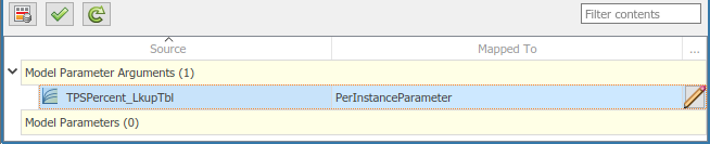
If you select a parameter type other than
Auto, you can click the icon to view and modify other code and
calibration attributes for the parameter.Attribute Purpose ShortName Specify a short name for the AUTOSAR parameter. If unspecified, ARXML export generates a short name based on the Simulink parameter name. Short names are not supported for port-based parameters (
PortParameter) since the port name can be used across multiple applications.Const ( ConstantMemoryonly)Select or clear the option to indicate whether to include C type qualifier constin generated code for the AUTOSAR parameter. For more information, see Specify C Type Qualifiers for AUTOSAR Static and Constant Memory.Volatile ( ConstantMemoryonly)Select or clear the option to indicate whether to include C type qualifier volatilein generated code for the AUTOSAR parameter. For more information, see Specify C Type Qualifiers for AUTOSAR Static and Constant Memory.AdditionalNativeTypeQualifier ( ConstantMemoryonly)Specify an AUTOSAR additional native type qualifier to include in generated code for the AUTOSAR parameter. For example, my_qualifier. For more information, see Specify C Type Qualifiers for AUTOSAR Static and Constant Memory.SwAddrMethod Select a SwAddrMethodname from the names listed as valid for the AUTOSAR parameter. For example, the modelautosar_swc_counterdefines VAR. Code generation uses theSwAddrMethodname to group AUTOSAR parameters in a memory section for access by calibration and measurement tools. For more information, see Configure SwAddrMethod.SwCalibrationAccess Specify how calibration and measurement tools can access the AUTOSAR parameter. Valid access values include ReadOnly,ReadWrite, andNotAccessible. For more information, see Configure SwCalibrationAccess.DisplayFormat Specify a display format for the AUTOSAR parameter. For example, %5.1f. AUTOSAR display format specifications control the width and precision display for calibration and measurement data. For more information, see Configure DisplayFormat.Port ( PortParameteronly)Select the name of a parameter receiver port configured in the AUTOSAR Dictionary. DataElement ( PortParameteronly)Select the name of a parameter interface data element configured in the AUTOSAR Dictionary. LongName Specify a description for the parameter.
Map Data Stores to AUTOSAR Variables
On the Data Stores tab of the Code Mappings editor, you can map Simulink data store memory blocks to AUTOSAR variables for AUTOSAR run-time calibration. After creating data store memory blocks in your model, open the Code Mappings editor and select the Data Stores tab. Select data stores and map them to AUTOSAR variables, such as AUTOSAR-typed per-instance memory or AUTOSAR static memory.
For more information, see Configure AUTOSAR Per-Instance Memory and Configure AUTOSAR Static Memory.
The Data Stores tab lists each data store that you can map to an AUTOSAR variable. You can:
Map a Simulink data store by selecting the data store, and then selecting a menu value for an AUTOSAR variable type:
ArTypedPerInstanceMemory,StaticMemory, orAuto. If you specifyAutofor the data store, the code generator might eliminate or change the representation of relevant code for optimization purposes. If optimizations are not possible, the code generator applies the default configuration and uses the default internal data packaging for the model, which can be set withsetInternalDataPackaging. If you want to use a data store for calibration or other specific access, it is recommended that you map it explicitly.For example, here is the Local Data Stores tab for example model
autosar_bsw_sensor1.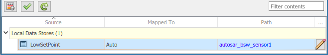
If you select a variable type other than
Auto, you can click the icon to view and modify other code and
calibration attributes for the variable.Attribute Purpose ShortName Specify a short name for the AUTOSAR variable. For example,
dsmsig. If unspecified, ARXML export generates a short name.Volatile ( StaticMemoryonly)Select or clear the option to indicate whether to include C type qualifier volatilein generated code for the AUTOSAR variable. For more information, see Specify C Type Qualifiers for AUTOSAR Static and Constant Memory.AdditionalNativeTypeQualifier ( StaticMemoryonly)Specify an AUTOSAR additional native type qualifier to include in generated code for the AUTOSAR variable. For example, my_qualifier. For more information, see Specify C Type Qualifiers for AUTOSAR Static and Constant Memory.NeedsNVRAMAccess ( ArTypedPerInstanceMemoryonly)Select or clear the option to indicate whether the AUTOSAR variable needs access to nonvolatile RAM on a processor. To configure the per-instance memory to be a mirror block for a specific NVRAM block, select the option. SwAddrMethod Select a SwAddrMethodname from the names listed as valid for the AUTOSAR variable. Code generation uses theSwAddrMethodname to group AUTOSAR variables in a memory section for access by calibration and measurement tools. For more information, see Configure SwAddrMethod.RestoreAtStart ( ArTypedPerInstanceMemoryonly)Select or clear the option to indicate if the state should be read out at startup. StoreAtShutdown ( ArTypedPerInstanceMemoryonlySelect or clear the option to indicate if the state written away at shutdown. SwCalibrationAccess Specify how calibration and measurement tools can access the AUTOSAR variable. Valid access values include ReadOnly,ReadWrite, andNotAccessible. For more information, see Configure SwCalibrationAccess.DisplayFormat Specify a display format for the AUTOSAR variable. For example, %5.1f. AUTOSAR display format specifications control the width and precision display for calibration and measurement data. For more information, see Configure DisplayFormat.LongName Specify a description for the variable.
Map Block Signals and States to AUTOSAR Variables
On the Signals/States tab of the Code Mappings editor, you can:
Map Simulink block signals and states to AUTOSAR variables for AUTOSAR run-time calibration.
Selectively add or remove block signals from AUTOSAR component signal mapping.
In the Code Mappings editor, Simulink block states that correspond to state owner blocks are available for mapping.
To make Simulink block signals available for mapping, use a Code Mappings editor button or a model cue:
In the model canvas, select one or more signals. Open the Code Mappings editor, Signals/States tab, and click the Add button
 .
.In the model canvas, select a signal. Place your cursor over the displayed ellipsis and select model cue Add selected signals to code mappings.
Alternatively, call MATLAB® function addSignal.
After selectively adding block signals to AUTOSAR component signal mapping, open the Code Mappings editor and select the Signals/States tab. Select block signals and states and map them to AUTOSAR variables, such as AUTOSAR-typed per-instance memory or AUTOSAR static memory.
For more information, see Configure AUTOSAR Per-Instance Memory and Configure AUTOSAR Static Memory.
Under the Signals/States tab, the Signals node lists each Simulink block signal that you can map to an AUTOSAR variable. The States node lists each configurable Simulink block state that you can map to an AUTOSAR variable.
To map a Simulink block signal or state, select it and then select a menu value for an
AUTOSAR variable type: ArTypedPerInstanceMemory,
StaticMemory, or Auto. If
you specify Auto for the signal or state, the code
generator might eliminate or change the representation of relevant code for
optimization purposes. If optimizations are not possible, the code generator applies
the default configuration and uses the default internal data packaging for the
model, which can be set with setInternalDataPackaging. If you want
to use a signal or state for calibration or other specific access, it is recommended
that you map it explicitly.
For example, here is the Signals/States tab for example model
autosar_swc_counter.

If you map a signal or state to a variable type other than
Auto, you can click the ![]() icon to view and modify other code and
calibration attributes for the variable.
icon to view and modify other code and
calibration attributes for the variable.
| Attribute | Purpose |
|---|---|
| ShortName | Specify a short name for the AUTOSAR variable. For example,
|
Volatile
(StaticMemory only) | Select or clear the option to indicate whether to include C type
qualifier volatile in generated code for the
AUTOSAR variable. For more information, see Specify C Type Qualifiers for AUTOSAR Static and Constant Memory. |
AdditionalNativeTypeQualifier
(StaticMemory only) | Specify an AUTOSAR additional native type qualifier to include in
generated code for the AUTOSAR variable. For example,
my_qualifier. For more information, see Specify C Type Qualifiers for AUTOSAR Static and Constant Memory. |
| SwAddrMethod | Select a SwAddrMethod name from the names
listed as valid for the AUTOSAR variable. For example, the model
autosar_swc_counter defines VAR. Code
generation uses the SwAddrMethod name to group
AUTOSAR variables in a memory section for access by calibration and
measurement tools. For more information, see Configure SwAddrMethod. |
| SwCalibrationAccess | Specify how calibration and measurement tools can access the
AUTOSAR variable. Valid access values include
ReadOnly,
ReadWrite, and
NotAccessible. For more information,
see Configure SwCalibrationAccess. |
| DisplayFormat | Specify a display format for the AUTOSAR variable. For example,
%5.1f. AUTOSAR display format specifications
control the width and precision display for calibration and
measurement data. For more information, see Configure DisplayFormat. |
| LongName | Specify a description for the AUTOSAR variable. |
To remove Simulink block signals from AUTOSAR component signal mapping, use a Code Mappings editor button or a model cue:
In the model canvas or on the Signals/States tab, select one or more signals. On the Signals/States tab, click the Remove button
 .
.In the model canvas, select a signal. Place your cursor over the displayed ellipsis and select model cue Remove selected signals from code mappings.
Alternatively, call MATLAB function removeSignal.
Map Data Transfers to AUTOSAR Inter-Runnable Variables
The Data Transfers tab of the Code Mappings editor supports modeling AUTOSAR inter-runnable variables (IRVs) in Simulink. After using the AUTOSAR Dictionary to create AUTOSAR IRVs, which connect runnables and implement aspects of internal behavior in an AUTOSAR component, open the Code Mappings editor. Use the Data Transfers tab to map Simulink data transfer lines to AUTOSAR IRVs.
For more information, see Model AUTOSAR Component Behavior. For illustrations of how IRVs are used with rate-based and function-call-based runnables, see the example models in Model AUTOSAR Software Components.
The Data Transfers tab of the Code Mappings editor maps each
Simulink data transfer line to an AUTOSAR IRV. Click the
Update button ![]() to load or update Simulink data transfers in your model.
to load or update Simulink data transfers in your model.
In the Data Transfers tab, you can map a Simulink data transfer line by selecting the signal name and then selecting
menu values for an IRV access mode (Implicit or
Explicit) and an AUTOSAR IRV name, among those listed
for the AUTOSAR component.
For example, here is the Data Transfers tab for example model
autosar_swc_slfcns.

Map Function Callers to AUTOSAR Client-Server Ports and Operations
The Function Callers tab of the Code Mappings editor supports modeling the client side of AUTOSAR client-server (C-S) communication in Simulink. After using the AUTOSAR Dictionary to create AUTOSAR client ports, C-S interfaces, and C-S operations in your model, open the Code Mappings editor. Use the Function Callers tab to map Simulink function callers to AUTOSAR client ports and AUTOSAR C-S operations.
For more information, see AUTOSAR Client-Server Communication.
The Function Callers tab of the Code Mappings editor maps
each Simulink function caller to an AUTOSAR client port and an AUTOSAR C-S interface
operation. Click the Update button ![]() to load or update Simulink function callers in the model.
to load or update Simulink function callers in the model.
In the Function Callers tab, you can map a Simulink function caller by selecting the function caller name and then selecting menu values for an AUTOSAR client port and an AUTOSAR operation, among those listed for the AUTOSAR component.

Specify C Type Qualifiers for AUTOSAR Static and Constant Memory
For an AUTOSAR component, you can configure C type qualifiers to customize
generated AUTOSAR-compliant C code for AUTOSAR static memory and AUTOSAR constant
memory. For example, you can apply C type qualifiers such as
const or volatile to control compiler
optimizations.
In an AUTOSAR model, use the Code Mappings editor to configure C type qualifiers
for model signals, states, data stores, and parameters that are mapped to AUTOSAR
StaticMemory or AUTOSAR
ConstantMemory. Building the model exports type
qualifiers to ARXML files and generates AUTOSAR-compliant C code that uses the type
qualifiers.
For example, in the Code Mappings editor, Signals/States tab,
suppose that you map a signal to StaticMemory. Select the
signal and click the ![]() icon to display additional code
attributes.
icon to display additional code
attributes.

If you select the Volatile attribute and specify
AdditionalNativeTypeQualifier to be
my_qualifier:
Exported ARXML files define the
AdditionalNativeTypeQualifier:<ADDITIONAL-NATIVE-TYPE-QUALIFIER>volatile my_qualifier</ADDITIONAL-NATIVE-TYPE-QUALIFIER>
Generated C code uses the C type qualifiers, for example:
/* Static Memory for Internal Data */
volatile my_qualifier boolean SM_equal_to_count;
For more information, see Map Block Signals and States to AUTOSAR Variables, Map Data Stores to AUTOSAR Variables, and Map Model Workspace Parameters to AUTOSAR Component Parameters.
Specify Default Data Packaging for AUTOSAR Internal Variables
AUTOSAR Blockset provides functions to control the default data packaging used for internal variables in the generated code for an AUTOSAR component model.
For models configured with a single instance of an AUTOSAR software component, you can specify that internal data store, signal, and state data are packaged:
With or without packing it in a structure
With private or public visibility
For AUTOSAR software components that are instantiated multiple times and configured to generate reentrant, reusable code, you can specify that internal variables are packaged to use C-typed per-instance memory or AUTOSAR-typed per-instance memory.
The functions getInternalDataPackaging and
setInternalDataPackaging return and set the default data
packaging setting used for internal data stores, signals, and states in the
generated code for an AUTOSAR component model.
Valid setting values are:
For single-instance models:
Default— Accept the default internal data packaging provided by the software. UseDefaultfor submodels referenced from AUTOSAR component models.PrivateGlobal— Package internal variable data without astructand make it private (visible only tomodel.cPrivateStructure— Package internal variable data in astructand make it private (visible only tomodel.cPublicGlobal— Package internal variable data without astructand make it public (externdeclaration inmodel.hPublicStructure— Package internal variable data in astructand make it public (externdeclaration inmodel.h
For multi-instance models:
Default— Accept the default internal data packaging provided by the software. UseDefaultfor submodels referenced from AUTOSAR component models.CTypedPerInstanceMemory— Package internal variable data for each instance of an AUTOSAR software component to use C-typed per-instance memory in astructand make it public (declaration inmodel.hArTypedPerInstanceMemory— Package internal variable data for each instance of an AUTOSAR software component to use AUTOSAR-typed per-instance memory in astructand make it public (declaration inRte_Type.h). SettingArTypedPerInstanceMemoryis not supported for models that contain model references.When data packaging is set to
ArTypedPerInstanceMemory, code generation does not support bitfield optimizations. Configuration parametersBooleansAsBitfields,StateBitsets, andDataBitsetsmust be disabled for this configuration.
This example modifies the default data packaging setting used for internal
variables in the generated code for an AUTOSAR component model. First, it returns
the current internal data packaging setting for the model. Then it sets the internal
data packaging such that the code generator packages the internal variable data in a
struct and makes it private.
hModel = 'autosar_swc';
openExample(hModel);
slMap = autosar.api.getSimulinkMapping(hModel);
pkgSetting1 = getInternalDataPackaging(slMap)
setInternalDataPackaging(slMap,'PrivateStructure')
pkgSetting2 = getInternalDataPackaging(slMap)
pkgSetting1 =
    'Default'

pkgSetting2 =
    'PrivateStructure'
If the data packaging is set to PrivateGlobal or
PrivateStructure, building the model generates header file
model_private.hCompact.
If the model configuration option Generate separate internal data per entry-point function (Embedded Coder) is set for the AUTOSAR model, task-based internal data grouping overrides the AUTOSAR internal data packaging setting. However, the AUTOSAR setting determines the public or private visibility of the generated internal data groups.
For more information, see the getInternalDataPackaging and setInternalDataPackaging reference pages.