I/Q Imbalance
Apply I/Q imbalances to complex signal
Libraries:
Communications Toolbox /
RF Impairments and Components
Description
The I/Q Imbalance block applies in-phase and quadrature imbalances to a complex signal. This block applies an amplitude imbalance, a phase imbalance, and a DC offset to the in-phase and quadrature signal components. For more information, see I/Q Imbalance Implementation and Algorithms.
Examples
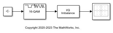
The cm_iq_imbalance_16qam model applies I/Q imbalance and DC offset impairments to a set of 16-QAM symbols, and then plots the signal constellation.
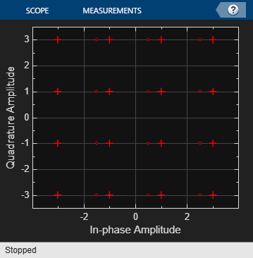
Display the signal constellation with zero values applied for all impairments. The signal samples and the reference constellation points align and overlay with each other in the constellation diagram.

Display the signal constellation with amplitude imbalance impairment only. The 16-QAM constellation elongates to a rectangular shape.
The amplitude imbalance is: 3.00 dB.

Display the signal constellation with phase imbalance impairment only. The 16-QAM constellation shifts to a rhombus shape.
The phase imbalance is: 30.00 degrees.

Display the signal constellation with in-phase DC offset impairment only. The 16-QAM constellation translates in the direction of the in-phase DC offset.
The in-phase DC offset is: 1.50.
Display the signal constellation with quadrature DC offset impairment only. The 16-QAM constellation translates in the direction of the quadrature DC offset.
The quadrature DC offset is: 1.50.

Impairments can be applied as negative values. Display the signal constellation with all imbalance impairments set to nonzero negative values.
The amplitude imbalance is: -3.00 dB.
The phase imbalance is: -30.00 degrees.
The in-phase DC offset is: -1.50.
The quadrature DC offset is: -1.50.

This example shows how to use the I/Q Imbalance Compensator block to remove the effects of an amplitude and phase imbalance on a modulated signal.
Explore Model
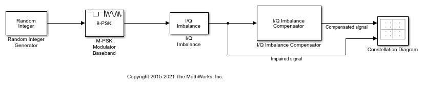
The model adds I/Q amplitude and phase imbalance to an 8-PSK signal, and then applies I/Q imbalance compensation to correct the impairments. Impairment addition and compensation performed on the signal by using the I/Q Imbalance and I/Q Imbalance to Compensator Coefficient blocks, respectively. The I/Q Imbalance block sets the amplitude imbalance to 5 dB, the phase imbalance to 7 degrees, and DC offset to 0.
The Constellation Diagram block displays the 8-PSK reference constellation, and the signal constellation before and after impairment correction.
Run Model and Display Measurements
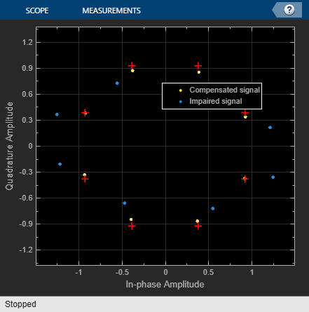
Run the model for 20 seconds, which is not long enough for the impairment compensation to converge. The reference constellation is plotted with red plus signs (+). The impaired signal plots the effects of the amplitude and phase imbalance on the 8-PSK signal. The compensated signal shows that the signal is not well aligned with the reference constellation.

The compensation algorithm is adaptive and requires time to accurately estimate the I/Q imbalance. Increase the simulation time to 100 seconds and rerun the model. You can see that the constellation is now well aligned with the reference constellation.
Further Exploration
You can try changing other simulation parameters, such the step size in the I/Q Imbalance Compensator block, the amplitude and phase imbalance in the I/Q Imbalance block, the modulation type. Then, observe the effects on the Compensated Signal constellation diagram.
Ports
Input
Output
Parameters
Block Characteristics
Data Types |
|
Multidimensional Signals |
|
Variable-Size Signals |
|
More About
The I/Q Imbalance block applies amplitude imbalance, phase imbalance, and DC offsets to the in-phase and quadrature components of the complex input signal.
The block performs these operations consecutively, as shown by the subsystem in this model diagram. You can view the subsystem by right-clicking the block and selecting Mask > Look inside mask.
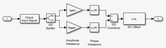
To apply the impairments, the block follows this workflow.
Separate the signal into its in-phase and quadrature components.
Apply amplitude imbalance, specified by the I/Q amplitude imbalance (dB) parameter.
Apply phase imbalance, specified by the I/Q phase imbalance (deg) parameter.
Recombine the in-phase and quadrature components into a complex signal.
Apply an in-phase DC offset, specified by the I dc offset parameter, and a quadrature DC offset, specified by the Q dc offset parameter, to the signal.
For more information, see Algorithms.
Algorithms
The I/Q amplitude imbalance, I/Q phase imbalance, and DC offset impairments are described sequentially in the section.
For an I/Q amplitude imbalance, Ia, the impairment is applied to the input signal, xr+ jxi and y AmplitudeImbalance is an intermediate output.
y AmplitudeImbalance y rAmplitudeImbalance + jyiAmplitudeImbalance
y AmplitudeImbalance =
For an I/Q phase imbalance, Ip, the impairment is applied to y AmplitudeImbalance and yPhaseImbalance is an intermediate output.
yPhaseImbalance yrPhaseImbalance + jyiPhaseImbalance
yPhaseImbalance =
For DC offsets, IDC and QDC, the impairment is applied to y PhaseImbalance and y is the final output.
y = (yrPhaseImbalance + IDC) + j(yiPhaseImbalance + QDC)
Variables for these calculations are defined in this list.
I a is the I/Q amplitude imbalance.
Ip is the I/Q phase imbalance.
IDC is the in-phase DC offset.
QDC is the quadrature DC offset.
x is the complex input signal and is given by xr + jxi.
xr and xi are the real and imaginary parts, respectively, of x.
y is the complex output signal and is given by yr + jyi.
yr and yi are the real and imaginary parts, respectively, of y.
Extended Capabilities
Version History
Introduced before R2006a
See Also
Blocks
- I/Q Compensator Coefficient to Imbalance | I/Q Imbalance Compensator | Free Space Path Loss | Memoryless Nonlinearity | Phase Noise | Receiver Thermal Noise