Control Onboard LED7 Brightness Using TSG3 Blocks on Renesas RH850 Microcontrollers
This example shows how to control the brightness of an onboard LED7 on the Embedded Coder ® Support Package for Renesas® RH850 Microcontrollers by varying the duty cycle of a TSG3 signal generated using TSG3 blocks. The workflow demonstrates how duty-cycle modulation directly affects LED intensity and how AUTOSAR MCAL configuration integrates with a Simulink model for hardware execution.
The example shows how to:
Generate a hardware TSG3 signal using the TSG31 timer module.
Control LED brightness by varying TSG3 duty cycle.
Deploy a pre-configured Simulink model to RH850 hardware.
Prerequisites
Before you begin,
Complete the Simulink Onramp tutorial.
Complete the Hardware Setup for Embedded Coder Support Package for Renesas RH850 Microcontrollers.
Required Hardware
RH850/U2A16 starter kit
Renesas E2 emulator
PC connection cable (USB Type-C)
Jumper wire
Hardware Connections
This example uses the onboard LED7 on the RH850/U2A16 starter kit.
Use a jumper wire to short P10_1 to P6_6 so that the configured TSG3 output is routed to the GPIO pin driving the onboard LED7.
MCAL Configuration Overview
The MCAL configuration for this example is stored in the configuration description file R7F702300x_tsg.arxml file.
DIO Module Configuration
The DIO module defines logical DIO channels and their mapping to hardware pins.
A DioPort group is configured for PortGroup6.
A DIO channel with the short name DioChannel_06_06 is defined.

The channel is assigned a bit position of
6, corresponding to pin 6 of Port Group 6
This channel represents the logical output that the Simulink model controls.
Port Module Configuration
The Port module defines pin-level behavior.
PortPin6 of PortGroup6 is configured
Pin initial mode is set to
Dio
Port Pin direction is set to output

TSG3 Configuration
Port pins P10_1 to P10_6 are configured for TSG31 module operation using the selected pin initial modes. This configuration allows the TSG31 outputs to drive the LEDs.

For more information on TSG3 configuration, see Getting Started with RH850 TSG3.
Configure the Simulink Model
Open the RH850TSG3GettingStarted.slx Simulink model.
modelName = "RH850TSG3GettingStarted";
open_system(modelName) 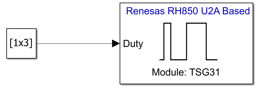
The model is pre-configured for Renesas RH850 U2A Based hardware.
Ensure the following settings are applied:
R7F702300x_tsg.arxmlis added as the configuration description file in Build options. To verify click Modeling > Model Settings to open the Configuration Parameters dialog box. Navigate to Hardware Implementation > Target hardware resources > Build options.

The model provides duty-cycle values to the AUTOSAR MCAL TSG3 interface, which configures the TSG31 timer hardware to generate TSG3 signals on the specified output channels.
TSG3 is configured as shown in this image.

Click Connectivity and verify the COM port settings.

Configure the Blocks
Constant block provides a 1-by-3 vector of duty-cycle values.
Double click the Constant block to open the block parameters dialog.

Each value represents the duty cycle (in percent) for a TSG3 output channel.
Higher duty-cycle values increase the average on-time of the signal.
Increased on-time results in higher average current through the LED7, producing greater perceived brightness.
For example, a duty-cycle value of 75 results in a brighter LED7 than a value of 50, while lower values reduce brightness accordingly.
Deploy Model to Hardware
Deploy the model to the target hardware and observe how TSG3 duty-cycle changes affect LED brightness in real time.
In the Simulink toolstrip, from the Hardware tab, click Monitor & Tune.

The code will be generated and the same will be automatically deployed to the RH850/U2A16 starter kit.
Observe LED Brightness Behavior
Once the application is running on the hardware, observe the LED7 on the RH850/U2A16 starter kit. The LED7 brightness varies according to the duty-cycle values provided to the TSG3 block, confirming correct TSG3 configuration and signal-to-hardware mapping.