Prepare a Model for Code Generation
Several standard methods are available for setting up a model to generate specific C
constructs in your code. For preparing your model for code generation, some of these methods
include: configuring signals and ports, initializing states, and setting up configuration
parameters for code generation. Depending on the components of your model, some of these
methods are optional. Methods for configuring a model to generate specific C constructs are
organized by category, for example, the Control Flow category includes constructs
if-else, switch, for, and
while. Refer to the name of a construct to see how you should configure
blocks and parameters in your model. Different modeling methodologies are available, such as
Simulink® blocks, Stateflow® charts, and MATLAB Function blocks, to implement a C
construct.
Model examples in Modeling Patterns for C Code Constructs have the following naming conventions:
| Model Components | Naming Convention |
|---|---|
| Inputs | u1, u2, u3, and so
on |
| Outputs | y1, y2, y3, and so
on |
| Parameters | p1, p2, p3, and so
on |
| States | x1, x2, x3, and so
on |
Input ports are named to reflect the signal names that they propagate.
Configure Input Ports, Output Ports, and Arbitrary Signals
Create a model in Simulink. For more information, see Interactive Model Editing.
On the Modeling tab, click Model Data Editor. You can also use the keyboard shortcut Ctrl + Shift + E.
Set the Change view drop-down list to
Design.Use the Storage Class column to apply a storage class to the signal.
For example, apply the storage class
ExportedGlobal, which makes the signal appear in the generated code as a separate global variable. The variable has the same name as the signal in the model.
Initialize and Configure States
In the Model Data Editor, on the States tab, use the Initial Value column to specify initial values for a block state (such as the state of a Unit Delay block).
Set the Change view drop-down list to
Code.Use the Name column to give the state a name.
Use the Storage Class column to apply a storage class to the state.
Set Up Configuration Parameters for Code Generation
On the C Code tab, click Settings to open the Configuration Parameters dialog box. You can also use the keyboard shortcut Ctrl + E.
Open the Configuration Parameter dialog box by selecting Simulation > Model Configuration parameters.
Open the Solver pane and select
Solver type:
Fixed-StepSolver:
discrete
                    (no continuous states)
Open the Optimization pane, and set Default parameter behavior to
Inlined.Open the Code Generation pane, and specify
ert.tlcas the System Target File.Clear Generate makefile.
Select Generate code only.
Enable the HTML report generation by opening the Code Generation > Report pane and selecting Create code generation report and Open report automatically. Click Advanced parameters and select Code-to-model. Enabling the HTML report generation is optional.
Click Apply and then OK to exit.
Set Up an Example Model With a Stateflow Chart
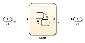
Follow this general procedure to create a simple model containing a Stateflow chart.
From the Stateflow > Chart library, add a Stateflow chart to your model.
Add Inport blocks and Outport blocks according to the example model.
Open the Stateflow Editor by performing one of the following:
Double-click the Stateflow chart.
Press Ctrl+R.
Add inputs to you chart as described in Add Stateflow Data (Stateflow).
Specify the Name
(u1, u2, ...)and the Type (Inherit: Same as Simulink) for each input, unless specified differently in the example.Add outputs to you chart as described in Add Stateflow Data (Stateflow).
Specify the Name
(y1, y2, ...)and Type (Inherit: Same as Simulink) for each output, unless specified differently in the example.In the Stateflow Editor, create the Stateflow diagram specific to the example.
The inputs and outputs appear on the chart in your model.
Connect the Inport and Outport blocks to the Stateflow Chart.
Configure the input and output signals; see Configure Input Ports, Output Ports, and Arbitrary Signals.
Set Up an Example Model With a MATLAB Function Block
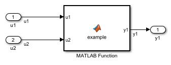
Add the number of Inport and Outport blocks according to a C construct example included in this chapter.
From the Simulink User-defined Functions library drag a MATLAB Function block into the model.
Double-click the block. The MATLAB Function Block Editor opens. Edit the function to implement your application.
On the Editor tab, click Save and close the MATLAB Function Block Editor.
Connect the Inport and Outport blocks to the MATLAB Function block. See Configure Input Ports, Output Ports, and Arbitrary Signals.
Save your model.