Main Content

Single-Acting Actuator (TL)

Single-acting linear actuator in a thermal liquid network

  • Single-Acting Actuator (TL) block

Libraries:
Simscape / Fluids / Thermal Liquid / Actuators

Description

The Single-Acting Actuator (TL) block models a linear actuator with a piston controlled by a single thermal liquid chamber. The actuator generates force in the extension and retraction strokes, but the actuation force depends on the gauge pressure at a single chamber.

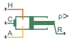
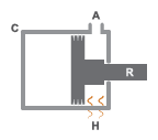
The figure shows the key components of an actuator. Port A represents the thermal liquid chamber inlet. Port R represents the translating actuator piston, and port C represents the actuator case. Port H represents the thermal interface between the thermal liquid chamber and the environment.

Single-Acting Actuator Schematic

Displacement

The block measures the piston displacement as the position at port R relative to port C. The Mechanical orientation parameter identifies the direction of piston displacement. The piston displacement is neutral, or 0, when the chamber volume is equal to the value of the Dead volume parameter. When the Piston displacement parameter is Provide input signal from Multibody joint, you input the piston displacement using port p. You can ensure that the derivative of the position signal is equal to the piston velocity by using a Translational Multibody Interface block to provide the piston displacement.

The direction of the piston motion depends on the Mechanical orientation parameter. If the mechanical orientation is positive, then the piston translation is positive in relation to the actuator case when the gauge pressure at port A is positive. The direction of motion reverses when the mechanical orientation is negative.

Hard Stop

A set of hard stops limit the piston range of motion. The block uses an implementation of the Translational Hard Stop block, which treats hard stops like spring-damper systems. The spring stiffness coefficient controls the restorative component of the hard-stop contact force and the damping coefficient the dissipative component.

The hard stops are located at the distal ends of the piston stroke. If the mechanical orientation is positive, then the lower hard stop is at x = 0, and the upper hard stop is at x = +stroke. If the mechanical orientation is negative, then the lower hard stop is at x = -stroke, and the upper hard stop is at x = 0.

Cushion

The block can model cushioning toward the extremes of the piston stroke. Select Cylinder end cushioning to slow the piston motion as it approaches the maximum extension, defined by the Piston stroke parameter. For more information on the functionality of a cylinder cushion, see the Cylinder Cushion (TL) block.

Friction

The block can model friction against piston motion. When you select Cylinder friction, the resulting friction is a combination of the Stribeck, Coulomb, and viscous effects. The block measures the pressure difference between the chamber pressure and the environment pressure. For more information on the friction model and its limitations, see the Cylinder Friction (TL) block.
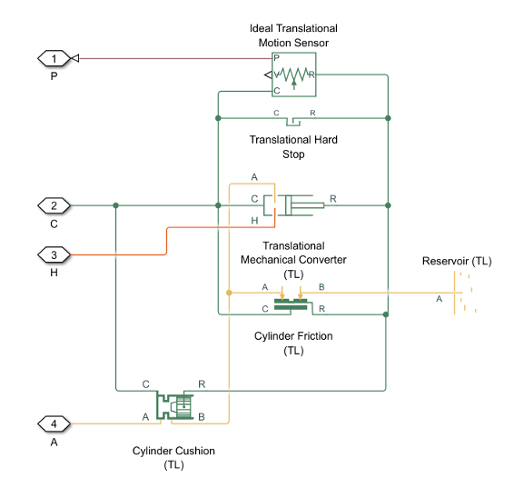
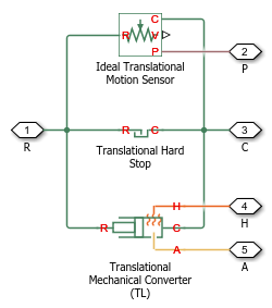
Block Composite

This block is a composite component based on these Simscape™ Foundation blocks:

Diagram of elements that make up the block.

If you select Cylinder friction or Cylinder end cushioning, the block composite also includes the Cylinder Friction (TL) block or Cylinder Cushion (TL) block.

Diagram of elements that make up the block with friction and cushion.

Ports

Input

expand all

Physical signal input associated with the piston position, in m. Connect this port to a Simscape Multibody™ network using a Translational Multibody Interface block.

Dependencies

To enable this port, set Piston displacement to Provide input signal from Multibody joint.

Output

expand all

Physical signal output associated with the piston position, in m.

Dependencies

To enable this port, set Piston displacement to Calculate from velocity of port R relative to port C.

Conserving

expand all

Thermal liquid conserving port associated with chamber A.

Translational mechanical conserving port associated with the actuator casing.

Translational mechanical conserving port associated with the actuator piston.

Thermal conserving port associated with the thermal mass of the liquid volume.

Parameters

expand all

Actuator

Piston displacement direction. When you set this parameter to:

  • Pressure at A causes positive displacement of R relative to C, the piston displacement is positive when the volume of liquid at port A is expanding. This motion corresponds to rod extension.

  • Pressure at A causes negative displacement of R relative to C, the piston displacement is negative when the volume of liquid at port A is expanding. This motion corresponds to rod contraction.

Cross-sectional area of the piston rod.

Maximum piston travel distance.

Volume of liquid when the piston displacement is 0. This parameter is the liquid volume when the piston is against the actuator end cap.

Environment reference pressure. When you select Atmospheric pressure, the block assumes a pressure of 0.101325 MPa.

User-defined environmental pressure.

Dependencies

To enable this parameter, set Environment pressure specification to Specified pressure.

Hard Stop

Hard stop model to use when the piston is at full extension or full extraction. See the Translational Hard Stop block for more information.

Piston stiffness coefficient.

Dependencies

To enable this parameter, set Hard stop model to one of these settings:

  • Stiffness and damping applied smoothly through transition region, damped rebound

  • Full stiffness and damping applied at bounds, undamped rebound

  • Full stiffness and damping applied at bounds, damped rebound

Piston damping coefficient.

Dependencies

To enable this parameter, set Hard stop model to one of these settings:

  • Stiffness and damping applied smoothly through transition region, damped rebound

  • Full stiffness and damping applied at bounds, undamped rebound

  • Full stiffness and damping applied at bounds, damped rebound

Application range of the hard stop force model. The block does not apply the hard stop model when the maximum extension or retraction of the piston is outside of this range. In this situation, there is no additional force on the piston.

Dependencies

To enable this parameter, set Hard stop model to Stiffness and damping applied smoothly through transition region, damped rebound.

Ratio of the final to the initial relative speed between the slider and the stop after the slider bounces.

Dependencies

To enable this parameter, set Hard stop model to Based on coefficient of restitution.

Threshold relative speed between the slider and stop before collision. When the slider hits the case with a speed less than the value of the Static contact speed threshold parameter, they stay in contact. Otherwise, the slider bounces. To avoid modeling static contact between the slider and the case, set this parameter to 0.

Dependencies

To enable this parameter, set Hard stop model to Based on coefficient of restitution.

Minimum force needed to release the slider from a static contact mode.

Dependencies

To enable this parameter, set Hard stop model to Based on coefficient of restitution.

Cushion

Whether to model piston slow-down at maximum extension. See the Cylinder Cushion (TL) block for more information.

Area of the plunger inside the actuator cushion element.

Dependencies

To enable this parameter, select Cylinder end cushioning.

Length of the cushion plunger.

Dependencies

To enable this parameter, select Cylinder end cushioning.

Area of the orifice between the cushion chambers.

Dependencies

To enable this parameter, select Cylinder end cushioning.

Gap area between the cushion plunger and sleeve. This value contributes to numerical stability by maintaining continuity in the flow.

Dependencies

To enable this parameter, select Cylinder end cushioning.

Pressure beyond which the valve operation is triggers. When the pressure difference between port A and Penv meets or exceeds the value of this parameter, the cushion valve begins to open.

Dependencies

To enable this parameter, select Cylinder end cushioning.

Maximum cushion valve differential pressure. This parameter provides an upper limit to the pressure so that system pressures remain realistic.

Dependencies

To enable this parameter, select Cylinder end cushioning.

Cross-sectional area of the cushion valve in the fully open position.

Dependencies

To enable this parameter, select Cylinder end cushioning.

Sum of all gaps when the cushion check valve is in the fully closed position. Any area smaller than this value saturates to the specified leakage area. This value contributes to numerical stability by maintaining continuity in the flow.

Dependencies

To enable this parameter, select Cylinder end cushioning.

Continuous smoothing factor that introduces a layer of gradual change to the flow response when the variable orifice and check valve are in near-open or near-closed positions. Set this value to a nonzero value less than one to increase the stability of your simulation in these regimes.

Dependencies

To enable this parameter, select Cylinder end cushioning.

Friction

Whether to model friction against piston motion. The block accounts for Coulomb, Stribeck, and viscous friction. See the Cylinder Friction (TL) block for more information.

Ratio of the breakaway force to the Coulomb friction force.

Dependencies

To enable this parameter, select Cylinder friction.

Threshold velocity for the motion against the friction force to begin.

Dependencies

To enable this parameter, select Cylinder friction.

Initial force in the cylinder due to the seal assembly.

Dependencies

To enable this parameter, select Cylinder friction.

Coulomb force coefficient of friction.

Dependencies

To enable this parameter, select Cylinder friction.

Viscous friction coefficient.

Dependencies

To enable this parameter, select Cylinder friction.

Initial Conditions

Method for determining the piston position. The block can receive the position from a Multibody block when set to Provide input signal from Multibody joint, or can calculate the position internally and report the position at port p. The position is between 0 and the value of the Piston stroke parameter when the mechanical orientation is positive and between 0 and the negative value of the Piston stroke parameter when the mechanical orientation is negative.

Piston position at the start of the simulation.

Dependencies

To enable this parameter, set Piston displacement to Calculate from velocity of port R relative to port C.

Whether to model any change in fluid density due to fluid compressibility. When you select Fluid compressibility, changes due to the mass flow rate into the block are calculated in addition to density changes due to changes in pressure. In the Isothermal Liquid Library, all blocks calculate density as a function of pressure.

Initial temperature of the liquid volume in the actuator.

Starting liquid pressure for compressible fluids.

Dependencies

To enable this parameter, select Fluid dynamic compressibility.

Extended Capabilities

C/C++ Code Generation
Generate C and C++ code using Simulink® Coder™.

Version History

Introduced in R2016a

expand all