NB-IoT Uplink Waveform Generation and Analysis
This example shows how to generate and receive a narrowband internet of things (NB-IoT) uplink waveform in the presence of an LTE wideband waveform. The example also analyzes the quality of the received NB-IoT physical uplink shared channel (NPUSCH) through error vector magnitude (EVM) measurements.
Introduction
To support maximum flexibility of the NB-IoT deployment, 3GPP defines these three NB-IoT modes of operation (TS 36.104 Section 3.1):
Standalone — NB-IoT carrier deployed in its own spectrum
Guardband — NB-IoT carrier deployed in the unused resource block(s) within an LTE carrier's guardband
In-band — NB-IoT carrier deployed in resource block(s) of an LTE carrier
This figure shows a sketch of in-band and guardband modes for a 5 MHz LTE carrier.
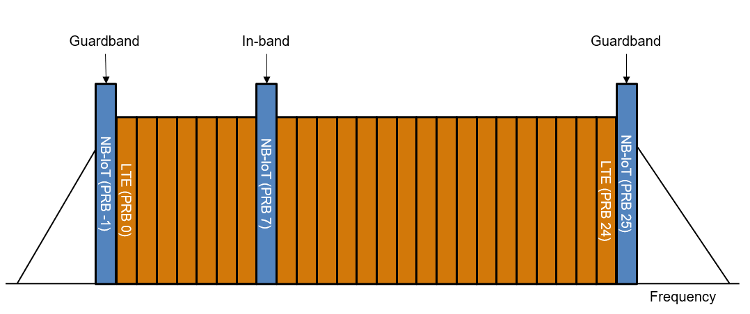
For the in-band mode of NB-IoT, the NB-IoT component should not overlap with any physical resource block (PRB) allocated for transmitting the physical uplink control channel (PUCCH).
For the guardband mode of NB-IoT, the allowed PRBs depend on the guardband size of the LTE carrier as defined in TS 36.101 Section 5.6. Guardband mode of NB-IoT is not supported on a 1.4 MHz and 3 MHz LTE carrier because the guardband sizes are too small. This table shows the allowed PRB indices for guardband deployment of uplink NB-IoT:
guardbandPRBTable = nbiotAllowedGuardbandPRB()
guardbandPRBTable=6×3 table
       LTE Bandwidth       Guardband PRBs (Lower Edge)    Guardband PRBs (Upper Edge)
    ___________________    ___________________________    ___________________________

    "1.4 MHz (  6 RBs)"        {1×0 double      }           {1×0 double           }
    "  3 MHz ( 15 RBs)"        {1×0 double      }           {1×0 double           }
    "  5 MHz ( 25 RBs)"        {[            -1]}           {[                 25]}
    " 10 MHz ( 50 RBs)"        {[         -2 -1]}           {[              50 51]}
    " 15 MHz ( 75 RBs)"        {[   -4 -3 -2 -1]}           {[        75 76 77 78]}
    " 20 MHz (100 RBs)"        {[-5 -4 -3 -2 -1]}           {[100 101 102 103 104]}
The example shows how to:
Generate an NB-IoT uplink waveform based on a reference test channel.
Receive the NB-IoT waveform in the presence of an LTE wideband waveform.
Measure NPUSCH EVM.
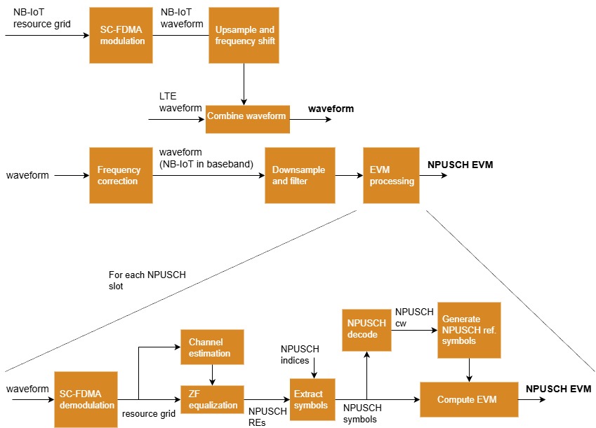
Generating the waveform and the processing it at the receiver to compute the NPUSCH EVM involves these steps:
Simulation Configuration
This example generates the NB-IoT uplink waveform based on a reference test channel, as defined in TS 36.104 Annex A. You can select a reference test channel with the desired subcarrier spacing and number of consecutive subcarriers in a resource unit (RU) for the NPUSCH configuration.
% TS 36.104, Base Station (BS) radio transmission and reception % Annex A.14 - Fixed Reference Channels for NB-IoT reference sensitivity (pi/2 BPSK, R=1/3) % Annex A.15 - Fixed Reference Channels for NB-IoT dynamic range (pi/4 QPSK, R=2/3) % Annex A.16 - Fixed Reference Channels for NB-IoT PUSCH format 1 rcname ="A14-1";
Select the number of uplink resource blocks (RBs), NULRB, and the index of the PRB for NB-IoT allocation, nbiotPRBIndex. To use the in-band operation mode for NB-IoT, specify nbiotPRBIndex as an integer between 0 and NULRB-1. To use the guardband operation mode for NB-IoT, specify nbiotPRBIndex with a valid value from guardbandPRBTable. Any other value of nbiotPRBIndex indicates that the NB-IoT will be out of band.
NULRB =25; nbiotPRBIndex =
-1;
Set the waveform duration in the number of transport blocks. The specified waveform duration applies to the LTE wideband waveform as well.
totNumTrBlks = 1;
NB-IoT Uplink Configuration and Waveform Generation
Use the local function configureNBIoTUplinkWaveform to configure the user equipment (UE) specific configuration, the NPUSCH channel specific configuration, and other required parameters.
ngen = configureNBIoTUplinkWaveform(NULRB,nbiotPRBIndex,RCName=rcname,TotNumTrBlks=totNumTrBlks);
Simulating guardband NB-IoT carrier
Use the local function generateNBIoTUplinkWaveform to generate the NB-IoT waveform. For details about this process, see the NB-IoT Uplink Waveform Generation example.
[nbiotWaveform,nbiotInfo] = generateNBIoTUplinkWaveform(ngen);
Generating 32 slots corresponding to 1 transport block(s) transmitted on NPUSCH
LTE Uplink Configuration and Waveform Generation
Configure and generate the LTE wideband waveform. Use the local function configureWidebandLTEWaveform to configure an LTE wideband waveform with the number of uplink RBs equal to NULRB.
ltecfg = configureWidebandLTEWaveform(NULRB,ngen.TotSubframes,nbiotPRBIndex);

% Generate wideband LTE waveform
trdata = [1 0 0 1];
[lteWaveform,~,lteInfo] = lteRMCULTool(ltecfg,trdata);
Waveform Combination
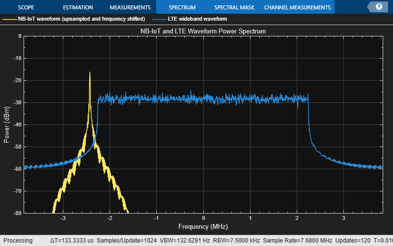
The example combines the NB-IoT and the LTE waveforms in the time domain assuming perfect synchronization between the two waveforms at the base station (BS). The hNBUplinkCombinedWaveform function applies frequency shifting to the NB-IoT waveform to put it in the specified PRB and upsamples the NB-IoT waveform before the combination. This function also plots the power spectra of the upsampled and frequency shifted NB-IoT waveform and the LTE wideband waveform.
% Create the parameter structure needed to combine the waveform
OSR = lteInfo.SamplingRate/nbiotInfo.SamplingRate;
combParams = struct();
combParams.NULRB = NULRB;
combParams.NBIoTPRBIndex = nbiotPRBIndex;
combParams.OSR = OSR;
combParams.SamplingRate = lteInfo.SamplingRate;

% Combine the waveform
[combWaveform,offset] = hNBUplinkCombinedWaveform(combParams,lteWaveform,nbiotWaveform);
NB-IoT Receive Filtering
In this section, you:
Apply frequency correction. Shift the received waveform in frequency to bring the NB-IoT spectrum to baseband (0 Hz).
Filter out the LTE component and downsample. Downsample the waveform to the NB-IoT sampling rate and filter out the frequencies outside the NB-IoT band.
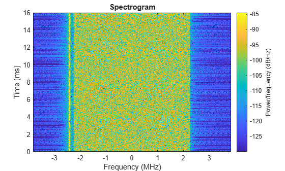
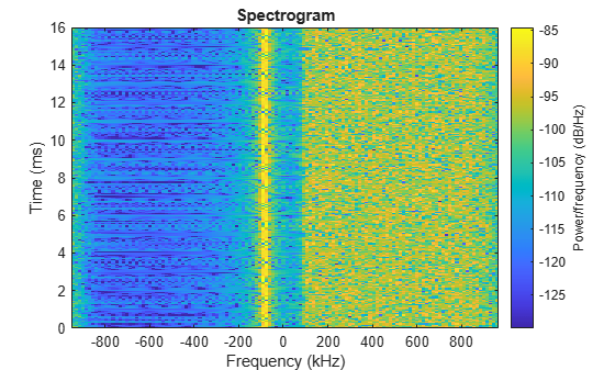
Plot the spectrogram of the received waveform. The plot shows the frequency occupied by the NB-IoT component in the received waveform.
rxWaveform = combWaveform;
minThreshold = -130 + 20 * double(strcmp(ngen.NBULSubcarrierSpacing,'3.75kHz')); % Threshold for spectrogram
figure;
spectrogram(rxWaveform(:,1),ones(lteInfo.Nfft,1),0,lteInfo.Nfft,'centered',lteInfo.SamplingRate,'MinThreshold',minThreshold);
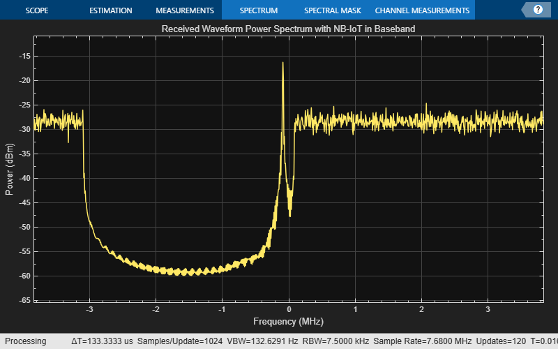
Downshifting of NB-IoT Waveform
Downshift the received waveform to bring the NB-IoT component to baseband. The plot shows the power spectrum of the received waveform after the frequency downshifting where the center of the PRB with the NB-IoT component is shifted to 0 Hz.
rxWaveformB = lteFrequencyCorrect(ltecfg,rxWaveform,offset); % Received waveform with NB-IoT in baseband
combinedSpecPlotB = spectrumAnalyzer('SampleRate',lteInfo.SamplingRate,'Title','Received Waveform Power Spectrum with NB-IoT in Baseband');
combinedSpecPlotB(rxWaveformB);
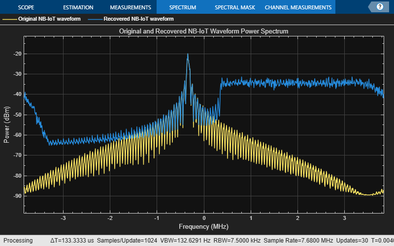
Filtering and Downsampling of NB-IoT Waveform
Use the resample function to downsample the baseband received waveform to the nominal NB-IoT sampling rate of 1.92 MHz. The default FIR antialiasing lowpass filter implemented in the resample function filters out the unwanted LTE component without using an additional lowpass filter.
rxwave = resample(rxWaveformB,1,OSR);
Plot the spectrogram of the recovered NB-IoT waveform against the original NB-IoT waveform.
filteredSpecPlot = spectrumAnalyzer('SampleRate',lteInfo.SamplingRate,'Title','Original and Recovered NB-IoT Waveform Power Spectrum', ...
    'ChannelNames',{'Original NB-IoT waveform','Recovered NB-IoT waveform'},'ShowLegend',true);
filteredSpecPlot([nbiotWaveform,rxwave]);
Plot the spectrogram of the recovered NB-IoT waveform. The plot shows the baseband narrowband waveform after extracting it from the received waveform.
figure;
spectrogram(rxwave(:,1),ones(nbiotInfo.Nfft,1),0,nbiotInfo.Nfft,'centered',nbiotInfo.SamplingRate,'MinThreshold',minThreshold);
EVM Measurements
Channel Estimator Configuration for EVM Measurements
Parameterize the channel estimator at the receiver end using the structure cec.
cec = struct();
cec.PilotAverage = 'UserDefined';   % Type of pilot symbol averaging
cec.FreqWindow = 23;                % Frequency window size in REs
cec.TimeWindow = 1;                 % Time window size in REs
cec.InterpType = 'Cubic';           % 2D interpolation type
cec.CELength = 1;                   % Channel estimation length in ms
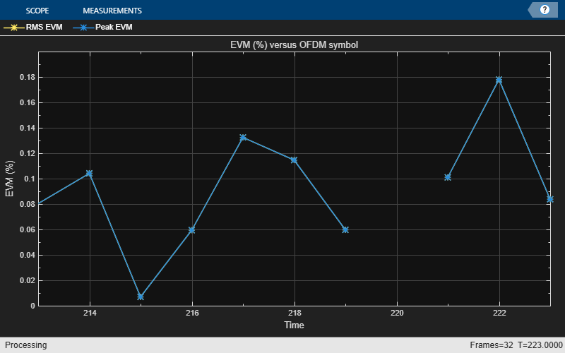
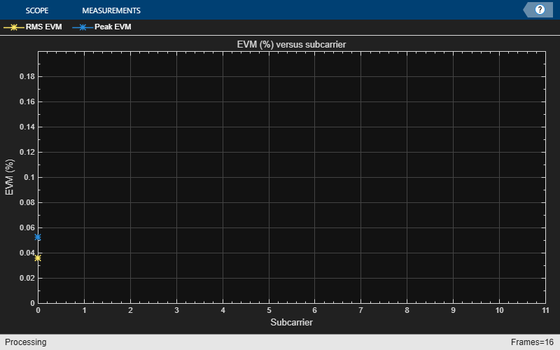
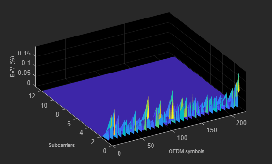
Process EVM
The hNPUSCHEVM function provides per slot and overall EVM measurements.
[evmmeas,plots] = hNPUSCHEVM(ngen,cec,rxwave,nbiotInfo);
Slot  0: average EVM 0.054%, peak EVM 0.078%
Slot  1: average EVM 0.094%, peak EVM 0.152%
Slot  2: average EVM 0.076%, peak EVM 0.119%
Slot  3: average EVM 0.033%, peak EVM 0.054%
Slot  4: average EVM 0.069%, peak EVM 0.088%
Slot  5: average EVM 0.057%, peak EVM 0.076%
Slot  6: average EVM 0.075%, peak EVM 0.121%
Slot  7: average EVM 0.053%, peak EVM 0.078%
Slot  8: average EVM 0.047%, peak EVM 0.066%
Slot  9: average EVM 0.116%, peak EVM 0.174%
Slot 10: average EVM 0.050%, peak EVM 0.068%
Slot 11: average EVM 0.057%, peak EVM 0.098%
Slot 12: average EVM 0.097%, peak EVM 0.138%
Slot 13: average EVM 0.065%, peak EVM 0.077%
Slot 14: average EVM 0.034%, peak EVM 0.048%
Slot 15: average EVM 0.123%, peak EVM 0.182%
Slot 16: average EVM 0.055%, peak EVM 0.097%
Slot 17: average EVM 0.089%, peak EVM 0.117%
Slot 18: average EVM 0.092%, peak EVM 0.123%
Slot 19: average EVM 0.072%, peak EVM 0.125%
Slot 20: average EVM 0.082%, peak EVM 0.127%
Slot 21: average EVM 0.063%, peak EVM 0.107%
Slot 22: average EVM 0.046%, peak EVM 0.075%
Slot 23: average EVM 0.040%, peak EVM 0.054%
Slot 24: average EVM 0.067%, peak EVM 0.105%
Slot 25: average EVM 0.074%, peak EVM 0.092%
Slot 26: average EVM 0.045%, peak EVM 0.088%
Slot 27: average EVM 0.058%, peak EVM 0.089%
Slot 28: average EVM 0.052%, peak EVM 0.092%
Slot 29: average EVM 0.036%, peak EVM 0.052%
Slot 30: average EVM 0.076%, peak EVM 0.108%
Slot 31: average EVM 0.118%, peak EVM 0.178%
All 32 slots: average EVM 0.072%, peak EVM 0.182%
References
3GPP TS 36.104. "Evolved Universal Terrestrial Radio Access (E-UTRA); Base Station (BS) Radio Transmission and Reception." 3rd Generation Partnership Project; Technical Specification Group Radio Access Network.
3GPP TS 36.211. "Evolved Universal Terrestrial Radio Access (E-UTRA); Physical Channels and Modulation." 3rd Generation Partnership Project; Technical Specification Group Radio Access Network.
3GPP TS 36.213. "Evolved Universal Terrestrial Radio Access (E-UTRA); Physical Layer Procedures." 3rd Generation Partnership Project; Technical Specification Group Radio Access Network.
Local Functions
function t = nbiotAllowedGuardbandPRB()
    % Generate a table showing the PRB indices allowed for NB-IoT guardband
    % deployment which depend on guardband sizes

    NULRBList = [6 15 25 50 75 100]; % TS 36.101 Section 5.6
    bwMHz = [1.4 3 5 10 15 20]; % Bandwidth in MHz
    bw = (pad(string(bwMHz),'left') + repmat(" MHz (",size(bwMHz)) + pad(string(NULRBList),'left') + repmat(" RBs)",size(bwMHz)))';

    % Guardband mode
    % The allowed PRB indices for NB-IoT guardband mode are derived
    % here for all channel bandwidths.
    totalGuardHz = bwMHz*1e6 - NULRBList*12*15e3; % Total guardband in Hz
    NRBGuard = floor((totalGuardHz/2) / (12*15e3)); % Number of RBs allowed on each side of the guardband for all BWs
    PRBGuardLow = cellfun(@(x) (-x:-1),num2cell(NRBGuard(:)),'UniformOutput',false); % Allowed PRB indices for lower-edge guardband (0-based)
    PRBGuardHigh = cellfun(@(x,y) (y+(0:(x-1))),num2cell(NRBGuard(:)),num2cell(NULRBList(:)),'UniformOutput',false); % Allowed PRB indices for upper-edge guardband (0-based)

    t = table(bw,PRBGuardLow,PRBGuardHigh);
    t.Properties.VariableNames = ["LTE Bandwidth" "Guardband PRBs (Lower Edge)" "Guardband PRBs (Upper Edge)"];
end

function ngen = configureNBIoTUplinkWaveform(NULRB,nbiotPRBIndex,nvargs)
    % Configure the NB-IoT uplink waveform

    arguments
        % Number of uplink RBs, for reporting operation mode only
        NULRB
        % PRB index in which NB-IoT is deployed, for reporting operation
        % mode only
        nbiotPRBIndex
        % The RMC or FRC on which the configuration will be based, as
        % defined in TS 36.101 Annex A or TS 36.104 Annex A
        nvargs.RCName = 'A14-1';
        % Target first subcarrier index of the NPUSCH frequency allocation
        % in the PRB
        nvargs.SubcarrierOffset = 0;
        % Number of repetitions in each NPUSCH codeword
        nvargs.NRep = 1;
        % Narrowband physical layer cell identity (PCI)
        nvargs.NNCellID = 0;
        % Radio network temporary identifier of the UE
        nvargs.RNTI = 0;
        % NPUSCH DM-RS cyclic shift for multi-tone cases
        nvargs.DMRSCyclicShift = 0;
        % Total number of transport blocks to transmit in the waveform
        nvargs.TotNumTrBlks = 1;
        % RV offset signaled via DCI (TS 36.213 16.5.1.2)
        nvargs.RVDCI = 0;
        % Windowing for SC-FDMA modulation (TS 36.104 Table E.5.1-1a)
        nvargs.Windowing = 3;
        % NPUSCH power scaling in dB
        nvargs.NPUSCHPower = 0;
        % NPUSCH DM-RS power scaling in dB
        nvargs.NPUSCHDMRSPower = 0;
    end

    % Get primary independent parameters for the NPUSCH
    [ue,chs,tbs] = getBasicRMCDefinition(nvargs.RCName);

    % Set UE-wide parameters
    ue.NNCellID = nvargs.NNCellID;
    ue.DuplexMode = 'FDD';
    ue.Windowing = nvargs.Windowing;

    % Get the number of slots in a single RU according to TS 36.211 Table
    % 10.1.2.3-1
    if strcmpi(chs.NPUSCHFormat,'Data') % format 1
        if chs.NRUsc == 1
            NULSlots = 16;
        elseif any(chs.NRUsc == [3 6 12])
            NULSlots = 24 / chs.NRUsc; % giving 8/4/2 slots per RU at the associated number of subcarriers
        else
            error('Invalid number of subcarriers. NRUsc (%d) must be one of 1,3,6,12.',chs.NRUsc);
        end
    elseif strcmpi(chs.NPUSCHFormat, 'Control') % format 2
        NULSlots = 4;
    else
        error('Invalid NPUSCH format (%s). NPUSCH format must be ''Data'' or ''Control''', chs.NPUSCHFormat);
    end
    chs.NULSlots = NULSlots;

    % NPUSCH channel-specific parameters
    numSubcarriers = 12*15/str2double(ue.NBULSubcarrierSpacing(1:end-3));
    subcarrieroffset = min(nvargs.SubcarrierOffset,numSubcarriers-chs.NRUsc);
    chs.NBULSubcarrierSet = subcarrieroffset+(0:chs.NRUsc-1);
    chs.NRep = nvargs.NRep;
    chs.RNTI = nvargs.RNTI;
    chs.NSlotsPerBundle = chs.NRU*chs.NULSlots*chs.NRep;
    chs.CyclicShift = nvargs.DMRSCyclicShift;
    chs.SeqGroupHopping = 'off';
    chs.SeqGroup = 0;
    chs.SlotIdx = 0;
    chs.RVDCI = nvargs.RVDCI;
    chs.NPUSCHPower = nvargs.NPUSCHPower;
    chs.NPUSCHDMRSPower = nvargs.NPUSCHDMRSPower;

    % Set the DM-RS base sequence ID according to TS 36.211 Section
    % 10.1.4.1.2. DM-RS base sequence ID is used for the multi-tone case
    % (3, 6, 12 tones), while it has no effect for single-tone or disabled
    % sequence-group hopping cases.
    if chs.NRUsc == 3
        maxBaseSeqIdx = 12;
    elseif chs.NRUsc == 6
        maxBaseSeqIdx = 14;
    else
        maxBaseSeqIdx = 30;
    end
    chs.BaseSeqIdx = mod(ue.NNCellID,maxBaseSeqIdx);

    % Calculate waveform duration parameters to be used for waveform
    % generation
    if strcmpi(ue.NBULSubcarrierSpacing,'15kHz')
        NSlotsPerFrame = 20;
        NSlotsPerSubframe = 2;
    else
        NSlotsPerFrame = 5;
        NSlotsPerSubframe = 0.5;
    end
    TotNSlots = nvargs.TotNumTrBlks*chs.NSlotsPerBundle;
    TotSubframes = TotNSlots/NSlotsPerSubframe;

    % Set the configuration structure ngen
    ngen = ue;
    ngen.TBS = tbs;
    ngen.TotNumTrBlks = nvargs.TotNumTrBlks;
    ngen.TotNSlots = TotNSlots;
    ngen.TotSubframes = TotSubframes;
    ngen.NSlotsPerFrame = NSlotsPerFrame;
    ngen.NPUSCH = chs;

    % Report operation mode
    if any(nbiotPRBIndex == (0:NULRB-1))
        operationMode = 'in-band';
    else
        gbTable = nbiotAllowedGuardbandPRB();
        gbPRBs = [gbTable{contains(gbTable{:,1},string(NULRB)+" RBs"),2:3}{:}];
        if any(nbiotPRBIndex == gbPRBs)
            operationMode = 'guardband';
        else
            operationMode = 'out-of-band';
        end
    end
    fprintf('\nSimulating %s NB-IoT carrier\n',operationMode);
end

function [ue,chs,tbs] = getBasicRMCDefinition(rcname)
    % Get the primary independent parameters for the RMC from the RAN4
    % RMC/FRC specification tables

        persistent rclist nl;

        if isempty(rclist)

            % TS 36.104 A.14 Fixed Reference Channels for NB-IoT reference sensitivity (pi/2 BPSK, R=1/3)
            rclistA14 = struct( ...
                'RCName',compose('A14-%d',1:2), ...
                'TBS',32, ...
                'NBULSubcarrierSpacing',{'15kHz','3.75kHz'}, ...
                'NRUsc',1, ...
                'Modulation','BPSK', ...  % (pi/2) BPSK for single tone
                'NRU',2, ...  % Each NPUSCH instance is 2 RUs of 1x16 'subcarriers x slots x pi/2-BPSK'
                'NPUSCHFormat','Data' ...
                );

            % TS 36.104 A.15 Fixed Reference Channels for NB-IoT dynamic range (pi/4 QPSK, R=2/3)
            rclistA15 = struct( ...
                'RCName',compose('A15-%d',1:2), ...
                'TBS',104, ...
                'NBULSubcarrierSpacing',{'15kHz','3.75kHz'}, ...
                'NRUsc',1, ...
                'Modulation','QPSK', ...  % (pi/4) QPSK for a single tone
                'NRU',1, ...  % Each NPUSCH instance to 1 RU of 1x16 'subcarriers x slots x pi/4-QPSK'
                'NPUSCHFormat','Data' ...
                );

            % TS 36.104 A.16 Fixed Reference Channels for NB-IoT NPUSCH format 1
            % A.16.1 One PRB
            rclistA16_1 = struct( ...
                'RCName',compose('A16-%d',1:6), ...
                'TBS',{32,32,40,104,136,424}, ...
                'NBULSubcarrierSpacing',{'3.75kHz','15kHz','15kHz','15kHz','15kHz','15kHz'}, ...
                'NRUsc',{1,1,3,6,12,12}, ...
                'Modulation',{'BPSK','BPSK','QPSK','QPSK','QPSK','QPSK'}, ...
                'NRU',{2,2,1,1,1,5}, ...
                'NPUSCHFormat','Data' ...
                );
            % A16-7 uses 16QAM
            rclistA16_2 = struct( ...
                'RCName','A16-7', ...
                'TBS',280, ...
                'NBULSubcarrierSpacing','15kHz', ...
                'NRUsc',12, ...
                'Modulation','16QAM', ...
                'NRU',1, ...
                'NPUSCHFormat','Data' ...
                );

            % TS 36.101, Annex A.2.4 Reference Measurement Channels for UE Category NB1
            rclistA24 = struct( ...
                'RCName',compose('R-%d',1:7), ...
                'TBS',{32,40,32,40,72,72,72}, ...
                'NBULSubcarrierSpacing',{'3.75kHz','3.75kHz','15kHz','15kHz','15kHz','15kHz','15kHz'}, ...
                'NRUsc',{1,1,1,1,3,6,12}, ...
                'Modulation',{'BPSK','QPSK','BPSK','QPSK','QPSK','QPSK','QPSK'}, ...
                'NRU',{2,1,2,1,1,1,1}, ...
                'NPUSCHFormat','Data' ...
                );

            % Control (NPUSCH format 2) 'reference' channels (provided here for utility, not 3GPP defined)
            rclistControl = struct( ...
                'RCName',compose('Control-%d',1:2), ...
                'TBS',0, ...
                'NBULSubcarrierSpacing',{'3.75kHz','15kHz'}, ...
                'NRUsc',1, ...
                'Modulation','BPSK', ...
                'NRU',1, ...
                'NPUSCHFormat','Control' ...
                );

            % Combine all the sets of channel definitions into a single structure vector
            rclist = [rclistA14,rclistA15,rclistA16_1,rclistA16_2,rclistA24,rclistControl];
            nl = {rclist.RCName}; % Store all the RMC names contained in the above definitions

        end

        % Look-up the definition entry for the required FRC
        selection = rclist(strcmpi(rcname,nl));
        if isempty(selection)
            error('RC name must be one of %s.', join(string(nl),', '));
        end

        % Parameter field mapping function
        fv = @(y,v)setfield(y,v,selection.(v));

        % Create the UE-specific parameter structure
        ue = struct();
        ue = fv(ue,'NBULSubcarrierSpacing');

        % Create the NPUSCH channel-specific structure
        chs = struct();
        chs = fv(chs,'NPUSCHFormat');
        chs = fv(chs,'Modulation');
        chs = fv(chs,'NRUsc');
        chs = fv(chs,'NRU');

        % Return the associated TBS
        tbs = selection.TBS;
end

function [waveform,info] = generateNBIoTUplinkWaveform(ngen)
    % Generate the NB-IoT uplink waveform

    % Get parameters
    ue = ngen;
    chs = ngen.NPUSCH;
    TotNSlots = ngen.TotNSlots;
    tbs = ngen.TBS;
    NSlotsPerFrame = ngen.NSlotsPerFrame;

    % Get the slot grid
    emptySlotGrid = lteNBResourceGrid(ue);
    slotGridSize = size(emptySlotGrid);
    L = slotGridSize(2);

    % Initialization
    state = [];
    trblk = [];
    nbGrid = repmat(emptySlotGrid,1,TotNSlots);

    % Display the number of slots being generated
    fprintf('\nGenerating %d slots corresponding to %d transport block(s) transmitted on NPUSCH\n',TotNSlots,ngen.TotNumTrBlks);

    % Loop over slots
    for slotIdx = chs.SlotIdx+(0:TotNSlots-1)

        % Calculate the frame number and slot number within the frame
        ue.NFrame = fix(slotIdx/NSlotsPerFrame);
        ue.NSlot = mod(slotIdx,NSlotsPerFrame);

        if isempty(trblk)
            if strcmpi(chs.NPUSCHFormat,'Data')
                % UL-SCH encoding is done for the two RV values used for
                % transmitting the codewords. The RV sequence used is
                % determined from the rvDVI value signaled in the DCI and
                % alternates between 0 and 2 as given in TS 36.213 Section
                % 16.5.1.2

                % Determine the coded transport block size
                [~,npuschInfo] = lteNPUSCHIndices(ue,chs);
                outblklen = npuschInfo.G;

                if outblklen>0
                    % Define the transport block which will be encoded to
                    % create the codewords for different RV
                    trblk = randi([0 1],tbs,1);

                    % Create the codewords corresponding  to the two RV
                    % values used in the first and second block. This will
                    % be repeated till all blocks are transmitted
                    chs.RV = 2*mod(chs.RVDCI+0,2);                        % RV for the first block
                    cw = lteNULSCH(chs,outblklen,trblk);                  % CRC and Turbo coding
                    chs.RV = 2*mod(chs.RVDCI+1,2);                        % RV for the second block
                    cw = [cw lteNULSCH(chs,outblklen,trblk)]; %#ok<AGROW> % CRC and Turbo coding is repeated
                else
                    % If the coded transport block size is zero, there is
                    % no transmission in this slot
                    cw = zeros(0,1);
                end
            else
                trblk = randi([0 1],1); % 1 bit ACK;
                % For ACK, the same codeword is transmitted in every block
                % as defined in TS 36.212 Section 6.3.3
                cw = lteNULSCH(trblk);
            end
            blockIdx = 0; % First block to be transmitted
            thisCw = getCodewordBlock(cw,blockIdx);
        end

        % Initialize grid
        slotRange = (slotIdx-chs.SlotIdx)*L+(1:L);
        slotGrid = nbGrid(:,slotRange);

        % Encode NPUSCH and map to the slot grid
        npuschSym = lteNPUSCH(ue,chs,thisCw,state);
        npuschInd = lteNPUSCHIndices(ue,chs);
        slotGrid(npuschInd) = npuschSym*db2mag(chs.NPUSCHPower);

        % Create DM-RS sequence and map to the slot grid
        [dmrsSym,state] = lteNPUSCHDRS(ue,chs,state);
        dmrsInd = lteNPUSCHDRSIndices(ue,chs);
        slotGrid(dmrsInd) = dmrsSym*db2mag(chs.NPUSCHDMRSPower);

        % Insert this slot into the waveform grid
        nbGrid(:,slotRange) = slotGrid;

        % If a full block is transmitted, increment the clock counter so
        % that the correct codeword can be selected
        if state.EndOfBlk
            blockIdx = blockIdx+1;
            thisCw = getCodewordBlock(cw,blockIdx);
        end

        % Transport block count and re-initialization
        if state.EndOfTx
            trblk = [];
        end
    end % end of slot loop

    % Perform SC-FDMA modulation to create time domain baseband waveform
    ue.CyclicPrefixUL = 'Normal';
    [waveform,info] = lteSCFDMAModulate(ue,chs,nbGrid);
end

function cwOut = getCodewordBlock(cwIn,blockIdx)
    % Get the slice of the codeword related to the input block index
    cwOut = cwIn(:,mod(blockIdx,size(cwIn,2))+1);
end

function ltecfg = configureWidebandLTEWaveform(NULRB,TotSubframe,nbiotPRBIndex)
    % Configure and generate the wideband LTE waveform with the given
    % number of uplink RBs, NULRB, the total number of subframes,
    % TotSubframe, and the PRB index of the PRB reserved for NB-IoT
    % deployment, nbiotPRBIndex, based on a reference measurement channel
    % (RMC) as defined in TS 36.104 Annex A

    % Select a reference measurement channel (RMC) as template
    ltecfg = struct();
    ltecfg.RC = 'A1-3'; % TS 36.104 Annex A
    ltecfg.NULRB = NULRB;

    % Set waveform duration
    ltecfg.TotSubframes = TotSubframe;

    % Use full band frequency allocation for PUSCH, and reserve the PRB
    % deployed with the NB-IoT component when operating in the in-band mode
    prbSet = (0:NULRB-1)';
    prbSet(prbSet==nbiotPRBIndex) = [];
    ltecfg.PUSCH.PRBSet = prbSet;
end