Field Oriented Control of PMSM Using Interleaved Boost Power Factor Correction
This example shows how to implement power factor correction (PFC) using a boost converter with the C2000™ Microcontroller Blockset. The example uses the Texas Instruments F28069M controlCARD with high voltage motor control kit (TMDSHVMTRINSPIN).
Using this example, you can:
Implement PFC using an interleaved boost converter.
Integrate Field Oriented Control (FOC) of PMSM with input factor correction.
In this example you will learn:
Simulate PFC using a boost converter.
Run a motor as a load for PFC using QEP Encoder
Generate code for the controller and load it on the controlCARD.
Monitor signals using the host computer.
Required Hardware
F28069M controlCARD
PMSM BLY171D (For Motor Load)
Hardware Connections
For Resistive Load
The High voltage motor control kit (TMDSHVMTRINSPIN) configuration includes the following hardware components:
F28069M controlCARD
DC power supply
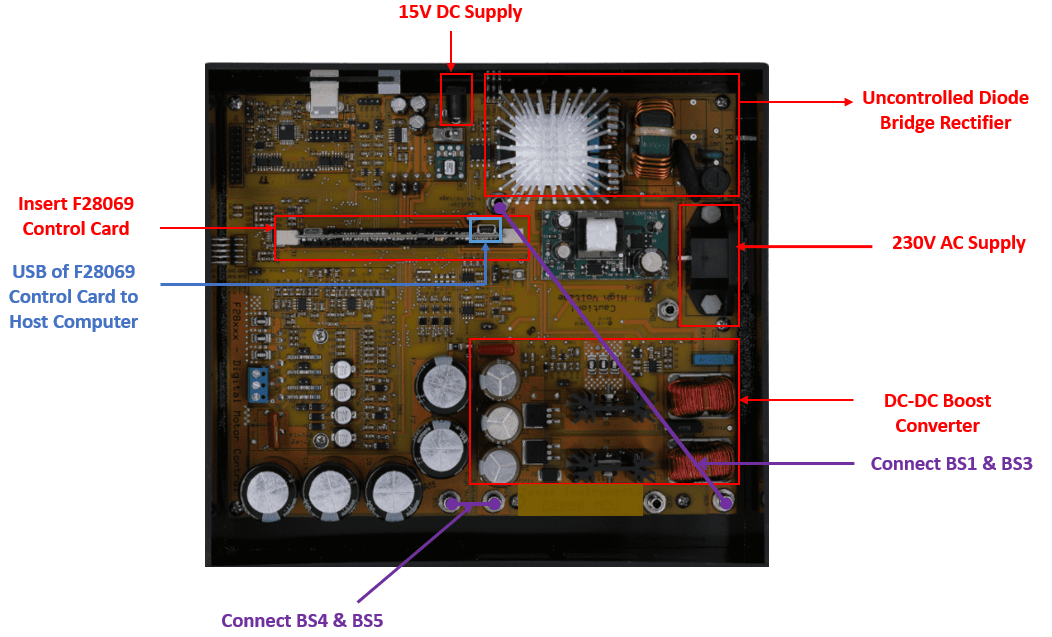
The following steps describe the jumper connections, switch settings and power supply connections for the High voltage motor control kit (TMDSHVMTRINSPIN):
Install the Jumpers [Main]-J3, J4 and J5, J9 for 3.3V, 5V and 15V power rails.
Unpack the DIMM style controlCARD and place it in the connector slot of [Main]-J1.
For controlCARDs with on-card isolated emulation, ex: TMDSCNCD28069MISO:
Populate M3-J5 on HV kit (disables power to HVKIT emulator)
Do NOT populate J9 on HV kit (disables JTAG connection)
On the F28069 ISO control card, ensure the following switch settings,
SW3: position 1 ON and position 2 ON.
SW2: position 1 OFF and position 2 OFF.res
SW1: position 1 ON and position 2 ON.
Connect 15V DC power supply to [M6]-JP1 and ensure that [M6]-SW1 is in the "Off" position.
Connect banana cable from [Main]-BS1 to [Main]-BS3 (This will connect the rectifier output to the boost converter input).
Connect banana cable from [Main]-BS4 and [Main]-BS5 (This will include the inverter DC bus capacitors in parallel to the PFC output stage capacitors).
Connect AC power to the [Main]-P1.
For Motor Load
The High voltage motor control kit (TMDSHVMTRINSPIN) configuration includes the following hardware components:
F28069M controlCARD
DC power supply
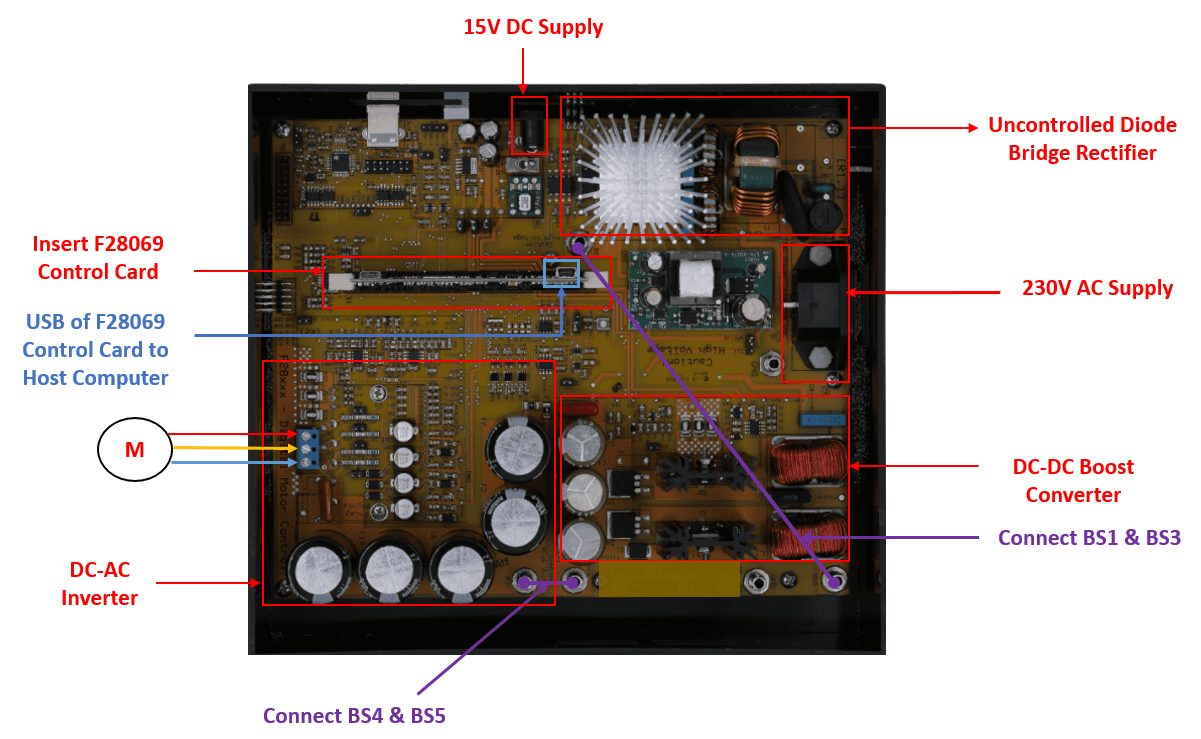
Ensure the connection described for the Motor load.
Connect the 3 phase motor terminals to MAIN-[TB3]
Connect the QEP terminals to the MAIN-[H1]. For more information, refer Quadrature Encoder Offset Calibration for PMSM Motor (C2000 Microcontroller Blockset)
Available Models
PMSMFOCUsingInterleavedBoostPFC— Simulate, generate code, and load it on the F28069M controlCARD for Motor Load model.PMSMFOCUsingInterleavedBoostPFCHost— Runs on the host computer to log signals for Motor Load Host model.
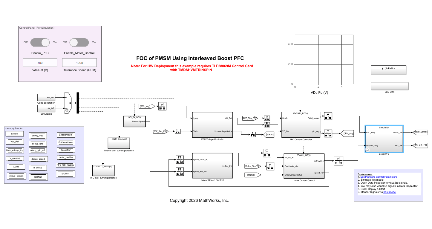
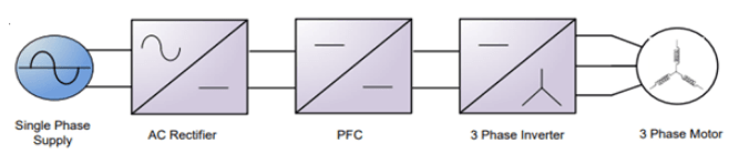
The model PMSMFOCUsingInterleavedBoostPFC consists of the plant model and the controller. The plant model consists of three major modules:
AC-DC Rectifier: This module takes 230 V to 230*sqrt(2) V AC input and outputs rectified DC voltage.
DC-DC Boost Converter: This module boosts up the input voltage based on the duty cycle of the pulse width modulation (PWM) output.
DC-AC Inverter: This module converts the DC input voltage into 3 phase AC voltage which is connected to the motor terminals.
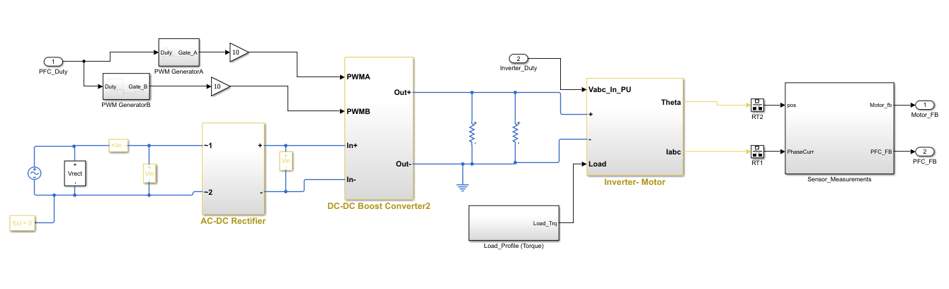
The AC-DC rectification stage uses a traditional uncontrolled H-bridge rectifier. The DC-DC boost converter on the kit has a two-phase interleaved topology. The duty cycle of the PWM output determines the amount of boost imparted to the input voltage.
The PFC controller provides current shaping of the AC input and regulates the DC bus. The outer voltage loop ensures that the output DC voltage is maintained at the set reference(400 V) by using a discrete proportional integral (PI) controller.
The inner current loop performs the wave shaping of the input AC current to maintain a high power factor. The reference for the current loop is generated by feed-forward of the rectified DC voltage as well as the output of the voltage control loop.
The output of the PFC controller is the PWM duty cycle of the DC-DC boost converter which is switched at 200 kHz. The controller operates at a rate of 100 kHz i.e. half of the PWM switching frequency.
The DC-DC Boost converter output voltage acts as input for the 3 phase inverter which in turn drives the 3 phase PMSM motor. In this model, the 3 phase inverter is switched at 10kHz and the FOC alogorithm is also executed at 10KHz. The motor is controlled using FOC where the motor position is sensed using the QEP Encoder.
The QEP offset for the motor used in the model can be calculated using different low voltage setup. For more, refer to QEP calibration. For more information, refer Quadrature Encoder Offset Calibration for PMSM Motor
The motor control is enabled when the output voltage of the boost converter reaches around 400 V.
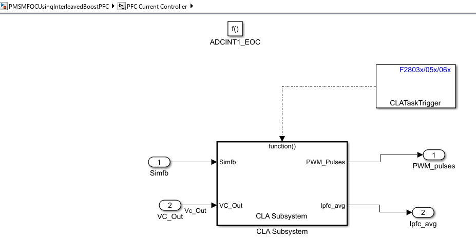
The PFC control algorithm for motor load is implemented inside CLA.
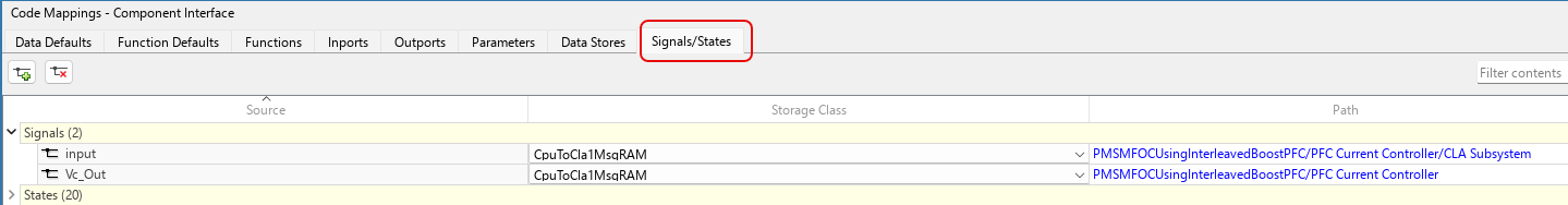
The signals/states/data stores required to be stored in the CLA memory space is done with the help of the Code Mappings - Component Interface of the Embedded Coder dictionary. The following image shows the elements in the model configured in CLA memory space.
Peripheral Block Configuration
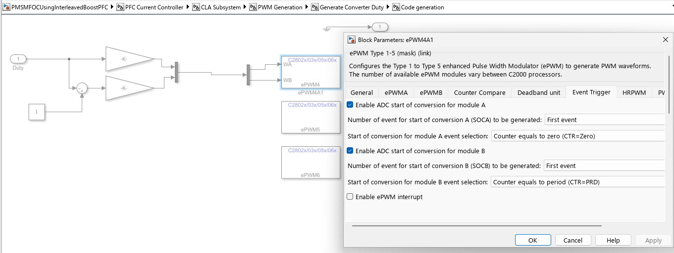
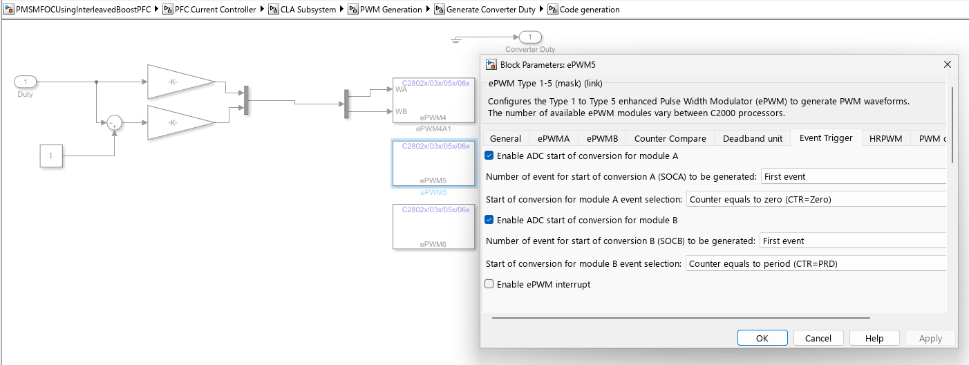
ePWM Block for PFC
The PWM signals are generated at a frequency of 200 kHz. The ePWM4 module is configured to operate in up-down count mode. All ADC results are read in (100kHz) ISR labeled PFC_ISR. This ISR is triggered by ePWM4 on every second of CMPB (with a preset value) match event during down count, so that the ISR is triggered only after the ADC conversions are complete.
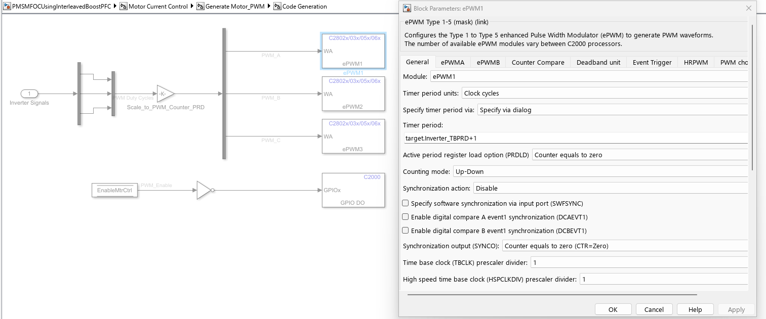
ePWM Block for Motor Load
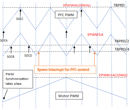
PWMs Synchronization and ADC Start of Conversion*
The motor PWM whose frequency is 10kHz generates a synchronization pulse at
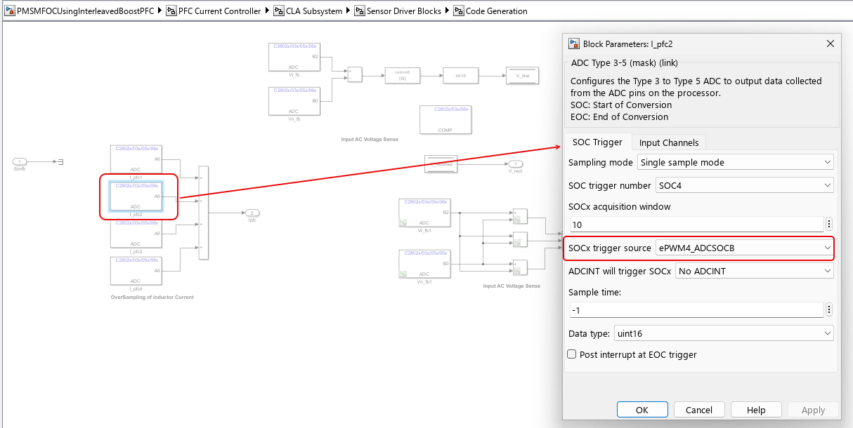
Counter=0for the PWM of PFC whose frequency is 200kHz.PFC total inductor current is sampled at the midpoint of the PWM ON pulse. Since the sampled value represents the average inductor current under CCM (continuous conduction mode) condition. PFC inductor current is also oversampled 4 times during each PWM time period. These 4 sampled values are then used to calculate the average PFC inductor current. The voltage signal conversions are also initiated when the PFC switch is on. The 4 SOC triggers are generated when,
ePWM4 counter reaches zero and period.
ePWM5 counter reaches a preset CMPA values during up and down count
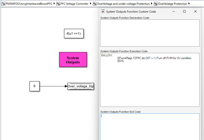
Overvoltage and Undervoltage Protection
An overvoltage protection mechanism is implemented using custom code in System Outputs block. The sensed DC bus output voltage from the ADC input is compared against the overvoltage protection threshold set in the initialization script file. Vpfc_trip_level is the overvoltage threshold point which is set to 430 V for the model. When overvoltage condition is met, the one-shot trip in ePWM is enabled.
Simulate PFC Using Boost Converter
Run the Model
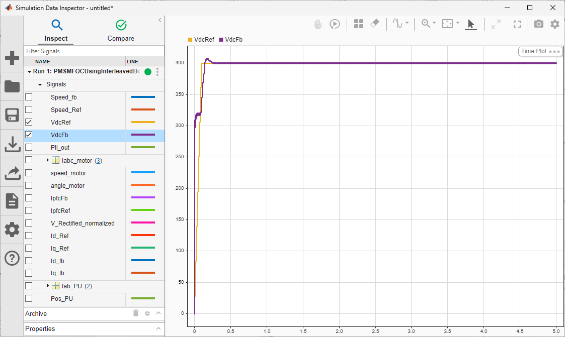
Open the
PMSMFOCUsingInterleavedBoostPFCmodel, and click the Run button to simulate the model.To observe the results, open Data Inspector to visualize signals.
Generate Code for Controller and Load It on controlCARD
The deployment model has a real-time interrupt service routines (ISR) configured to trigger PFC control at the rate of 100 kHz.
Ensure the hardware connections are made as mentioned in the Resistive Load Hardware Connections section.
Turn on [M6]SW1 on the kit to power on the controlCARD.
Open the model and generate code by pressing Ctrl+B.
Follow the build process by opening the diagnostic viewer using the link at the bottom of the model canvas.
Turn on the AC power supply and gradually increase the AC input ([Main]-P1) to the value between 230 V to 230*sqrt(2) V. The PFC algorithm kicks in when the AC input is more than 230 V.
The motor control is enabled, after a delay of 10sec when the boost converter output voltage reaches 400 V. By default, the motor starts spinning at speed of around 0.3 per unit.
Run the host model and observe the output capacitor voltage & the PFC inductor current.
Turn off the AC power first and wait for a few minutes for the PFC DC bus capacitor to discharge completely.
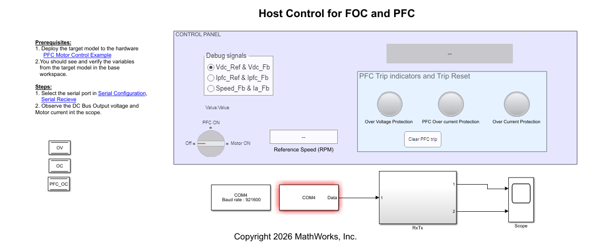
Monitor Signals on Host Computer
The host model receives the data from the hardware kit and plots it to verify the performance of the PFC controller.
On the host computer, browse to Device Manager > Ports (COM & LPT) to find the COM port.
Set the parameter Port of the following blocks in the model to match the COM port of the host computer:
Serial Configuration
Serial Receive
Click the Run button on the Simulation tab to run the host model.
While the model runs, you can monitor the boost converter output capacitor voltage and input inductor current to analyze the performance of PFC control.