Main Content

CAN Transmit

Transmit messages to controller area network (CAN) bus from ROS 2 network

Since R2026a

  • ROS 2 CAN Transmit Block Mask

Libraries:
ROS Toolbox / ROS 2

Description

This feature also requires the Vehicle Network Toolbox™ product when transmitting message as a structured CAN message.

The CAN Transmit block transmits messages to a CAN network using a real or virtual CAN interface on your target machine. It enables the Simulink® model to send data formatted as a raw uint8 vector, ROS 2 message, or a structured CAN message containing fields such as ID, length, and data. Use this block to transmit CAN messages in external mode execution and code generation workflows. For more information on how to set up a virtual CAN interface, see Set Up Virtual CAN Interface.

You can configure the block to wait for successful transmission (blocking mode) or to continue execution without waiting (non-blocking mode). The block is designed to work with ROS 2 nodes that support CAN device integration through supported drivers. It supports code generation and external mode workflows involving ROS 2 and CAN-enabled embedded systems.

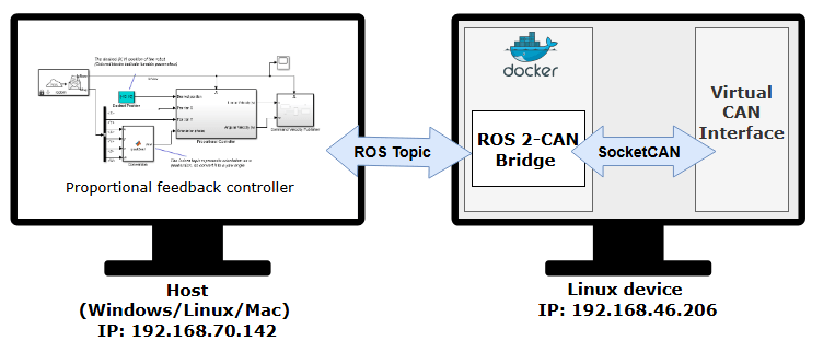
This image shows a ROS 2-CAN node that you can deploy on hardware. This node acts as a bridge between the CAN device and the ROS 2 network, thereby enabling the transmission and reception of CAN messages.

For the Raw Data input type, you can apply message filters such as Identifier type, Message ID, and Message length from the block dialog box parameters.

For the ROS Msg or CAN Msg input type, you can set message filters such as ID Type, Acceptance Mask, and Acceptance Filter using the steps listed in Configure CAN Interfaces and Apply Message Filtering.

Examples

Ports

Input

expand all

Message data, specified as one of these options:

  • Vector of data type uint8 to transmit the message as raw data.

  • Bus signal of type SL_Bus_mw_can_msgs_Frame to transmit the message as a ROS 2 message. The SL_Bus_mw_can_msgs_Frame type is a bus generated by Simulink that corresponds to the ROS message type mw_can_msgs/Frame. Simulink creates this bus automatically when you import the mw_can_msgs package using the ROS message importer. This type defines the fields of a CAN message exchanged between Simulink and ROS nodes.

    To transmit the message as a ROS 2 message, connect the input port to a Blank Message block from the ROS 2 library.

  • Bus signal of type CAN_MESSAGE_BUS to transmit the message as a structured CAN message. The CAN_MESSAGE_BUS type is a Simulink bus object that defines the structure of a CAN message used for communication. It is used as the signal interface between Simulink and the CAN protocol layers.

    To transmit the message as a structured CAN message, connect the input port to corresponding blocks from the Vehicle Network Toolbox to convert between sets of signal values and formatted CAN messages for communication in a CAN network.

Data Types: uint8 | ROS Msg | CAN Msg

Output

expand all

Message transfer status, returned as a scalar value. This port outputs 0 for when the transmission is successful and error codes in case of failure. The error codes are listed in this table.

0000ABTFMLOATXERRTXBOTXEPTXWAR
bit7bit6bit5bit4bit3bit2bit1bit0

ABTF: Message Aborted Flag bit

MLOA: Message Lost Arbitration bit

TXERR: Transmission Error Detected bit

TXBO: Bus-Off Error Flag bit

TXEP: Transmit Error-Passive Flag bit

TXWAR: Transmit Error Warning Flag bit

Dependencies

To enable this port, select the Output status parameter.

Parameters

expand all

To edit block parameters interactively, use the Property Inspector. From the Simulink Toolstrip, on the Simulation tab, in the Prepare gallery, select Property Inspector.

Interface name of the CAN controller, specified as a valid CAN device name. To find the name of the CAN interface, execute the ifconfig command in the host terminal.

Data type to use for transmitting messages, specified as one of these types —

  • Raw Data — To transmit the message as a uint8 vector array, set the Data input type parameter to Raw Data.

  • ROS Msg — To transmit the message as a ROS 2 message, set the Data input type parameter to ROS Msg. For Port1 to accept a ROS 2 message, connect the output of the Blank Message block to the input port of the CAN Transmit block.

  • CAN Msg — To transmit the message as a structured CAN message, set the Data input type parameter to CAN Msg. For Port1 to accept a CAN message packed using the CAN Pack block, connect the output of the CAN Pack block to the input port of the CAN Transmit block.

Select this parameter to enable the block to wait before transferring data You can set the waiting time in the Time out in seconds parameter.

Specify the waiting time for the block before transferring data. After this period, the block times out.

Dependencies

To enable this parameter, select Wait until data sent.

Select this parameter to indicate the status of message transfer at the output port.

Message identifier type, specified as Standard (11-bit identifier) or Extended (29-bit identifier).

Dependencies

To enable this parameter, set the Data input type parameter to Raw Data.

Message identifier specified as 11 bits for the standard frame size or 29 bits for the extended frame size, returned in decimal, binary, or hex value format. For binary and hex formats, use bin2dec(' ') and hex2dec(' '), respectively, to convert the entry. The message identifier is coded into a message that is sent to the CAN bus.

Dependencies

To enable this parameter, set the Data input type parameter to Raw Data.

Length of the message received by the block, specified as a positive integer value.

Dependencies

To enable this parameter, set the Data input type parameter to Raw Data.

Select this parameter to enable remote message by sending a request for remote frames.

Dependencies

To enable this parameter, set the Data input type parameter to Raw Data.

Extended Capabilities

expand all

Version History

Introduced in R2026a