Link-Level CCSDS Telemetry Synchronization and Channel Coding Simulation with RF Impairments and Corrections
This example shows how to measure the bit error rate (BER) of the link-level chain of the Consultative Committee for Space Data Systems (CCSDS) telemetry (TM) system. The simulation chain follows the coding and modulation schemes that are specified by these two standards:
Introduction
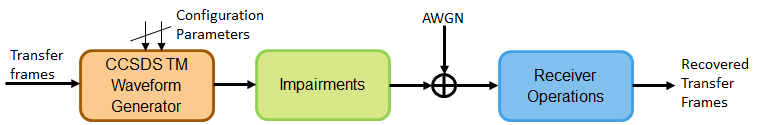
Data from various instruments is generated on board the satellite. This data is collectively called as TM data. CCSDS specifies the coding and modulation schemes for the transmission of TM data from the satellite to an Earth station. This example shows the link-level simulation of the satellite to the Earth station communication link. The example shows how to generate a complex baseband CCSDS TM waveform from the randomly generated transfer frames (TFs), introduce radio frequency (RF) impairments to the baseband signal, and add additive white Gaussian noise (AWGN) to the impaired signal. Then, the example shows the synchronization, demodulation, and decoding of this impaired noisy signal to get the final bits in the form of TFs. The example also shows how to measure the BER with respect to the signal-to-noise ratio (SNR) for one configuration of the CCSDS TM signal. This figure shows the link-level simulation chain.
This example models these RF impairments:
Carrier frequency offset (CFO)
Sampling rate offset (SRO)
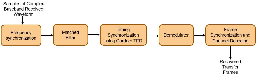
This figure shows the receiver side operations.
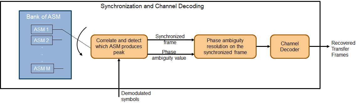
The frame synchronization and channel decoding processing step performs these three tasks.
Perform phase ambiguity resolution
Correctly synchronize the frame to the starting of the attached sync marker (ASM)
Perform channel decoding of the synchronized frame to get the recovered TF
This figure shows these three tasks. To start, form a bank of ASM sequences. Each sequence corresponds to the original ASM value in which phase ambiguity is introduced. Correlate each of these sequences with the demodulated symbols. Choose the phase ambiguity value that has the highest correlation peak. Perform the frame synchronization with this correlation process. The process to perform correlation is illustrated in section 9.3.7 in [3]. This example adopts the simplified Massey algorithm for frame synchronization. Resolve the phase ambiguity on the complete set of demodulated symbols after the frame synchronization process is complete. Finally, perform channel decoding on these symbols to obtain the recovered TFs.
Simulation Parameters
This example uses a quadrature phase shift keying (QPSK) modulation scheme for signal generation and reception and Reed Solomon (RS) coding scheme for channel coding. The link-level chain in this example can also be used for the channel coding schemes that are specified in [1]: convolutional and concatenated codes. For convolutional and concatenated codes, this example supports rates of 1/2 and 2/3 along with pulse code modulation (PCM)-format of non-return to zero-line (NRZ-L). The supported modulation schemes in this example are binary phase shift keying (BPSK), QPSK, and offset QPSK (OQPSK).
modScheme ="QPSK"; % Modulation scheme channelCoding =
"RS"; % Channel coding scheme if channelCoding == "convolutional" transferFrameLength =
892; % In bytes. 892 corresponds to 223*4 else % For RS or concatenated RSMessageLength =
223; RSInterleavingDepth =
4; % Any positive integer end rolloffFactor =
0.35; % Root raised cosine filter roll-off factor samplesPerSymbol =
4; % Samples per symbol showConstellation =
true; % To improve speed of execution, disable the visualization of constellation
Set the frequencies that are used for signal generation and the RF impairment values.
symbolRate =10000000; % Symbol rate or Baud rate in Hz carrierFrequencyOffset =
2e5; % In Hz
Initialize the energy per bit to noise power ratio (Eb/N0), which is used to calculate the SNR using system parameters.
EbN0 =  4:0.5:6.5;
Initialize the parameters to terminate the simulation. The parameters are set to small values in this example to get quick results. Increase these parameters value to get a smoother BER curve.
maxNumErrors =100; % Simulation stops after maxNumErrors bit errors % Set maxNumBits = 1e8 for a smoother BER curve maxNumBits =
1000000; % Simulation stops after processing maxNumBits maxFramesLost =
100; % Simulation stops after maxFramesLost frames are lost
Simulation Configuration
Initialize all of the objects that are required for the proper functioning of the link-level chain.
Create a CCSDS TM waveform generator with these parameters by using the ccsdsTMWaveformGenerator System object™. Display the properties of the object.
tmWaveGen = ccsdsTMWaveformGenerator( ...
    "Modulation",modScheme, ...
    "ChannelCoding",channelCoding, ...
    "RolloffFactor",rolloffFactor, ...
    "SamplesPerSymbol",samplesPerSymbol);

if channelCoding == "convolutional"
    tmWaveGen.NumBytesInTransferFrame = transferFrameLength;
else % For RS and concatenated codes
    tmWaveGen.RSMessageLength = RSMessageLength;
    tmWaveGen.RSInterleavingDepth = RSInterleavingDepth;
end
tmWaveGen
tmWaveGen =
  ccsdsTMWaveformGenerator with properties:

          WaveformSource: "synchronization and channel coding"
           HasRandomizer: true
                  HasASM: true
               PCMFormat: "NRZ-L"

   Channel coding
           ChannelCoding: "RS"
         RSMessageLength: 223
     RSInterleavingDepth: 4
    IsRSMessageShortened: false

   Digital modulation and filter
              Modulation: "QPSK"
      PulseShapingFilter: "root raised cosine"
           RolloffFactor: 0.3500
     FilterSpanInSymbols: 10
        SamplesPerSymbol: 4

  Show all properties
Calculate the SNR from the Eb/N0 and initialize the parameters related to the calculation of BER.
rate = tmWaveGen.info.ActualCodeRate;
M = tmWaveGen.info.NumBitsPerSymbol;
numBitsInTF = tmWaveGen.NumInputBits;
snr = EbN0 + 10*log10(rate) + ...
    10*log10(M) - 10*log10(samplesPerSymbol); % As signal power is scaled to one while introducing noise,
                                              % SNR value should be reduced by a factor of SPS
numSNR = length(snr);
ber = zeros(numSNR,1);                        % Initialize the BER parameter
bercalc = comm.ErrorRate;
Create a receive filter object by using the comm.RaisedCosineReceiveFilter System object.
b = rcosdesign(rolloffFactor,tmWaveGen.FilterSpanInSymbols,samplesPerSymbol);
% |H(f)| = 1  for |f| < fN(1-alpha) - Annex 1 in Section 2.4.17A in [2]
Gain =  sum(b);
rxFilterDecimationFactor = samplesPerSymbol/2;
rxfilter = comm.RaisedCosineReceiveFilter( ...
    "DecimationFactor",rxFilterDecimationFactor, ...
    "InputSamplesPerSymbol",samplesPerSymbol, ...
    "RolloffFactor",rolloffFactor, ...
    "Gain",Gain);
Model frequency and phase offsets by using the comm.PhaseFrequencyOffset System object. Compensate for frequency and phase offset at the receiver in two steps.
Compensate for the coarse frequency offset by using the
comm.CoarseFrequencyCompensatorSystem object.Compensate for the fine frequency offset and the phase offset by using the
comm.CarrierSynchronizerSystem object.
phaseOffset = pi/8;
fqyoffsetobj = comm.PhaseFrequencyOffset( ...
    "FrequencyOffset",carrierFrequencyOffset, ...
    "PhaseOffset",phaseOffset, ...
    "SampleRate",samplesPerSymbol*symbolRate);
coarseFreqSync = comm.CoarseFrequencyCompensator( ...
    "Modulation",modScheme, ...
    "FrequencyResolution",100, ...
    "SampleRate",samplesPerSymbol*symbolRate);
if modScheme == "OQPSK"
    coarseFreqSync.SamplesPerSymbol = samplesPerSymbol;
end
fineFreqSync = comm.CarrierSynchronizer("DampingFactor",1/sqrt(2), ...
    "NormalizedLoopBandwidth",0.0007, ...
    "SamplesPerSymbol",samplesPerSymbol, ...
    "Modulation",modScheme);
Create a sample rate offset object by using the comm.SampleRateOffset System object, which introduces the sampling rate offset in the transmitted waveform. Create a symbol synchronization object by using the comm.SymbolSynchronizer System object, which performs symbol timing synchronization.
samplerateoffsetobj = comm.SampleRateOffset;
Kp = 1/(pi*(1-((rolloffFactor^2)/4)))*cos(pi*rolloffFactor/2);
symsyncobj = comm.SymbolSynchronizer( ...
    "DampingFactor",1/sqrt(2), ...
    "DetectorGain",Kp, ...
    "TimingErrorDetector","Gardner (non-data-aided)", ...
    "Modulation","PAM/PSK/QAM", ...
    "NormalizedLoopBandwidth",0.0001, ...
    "SamplesPerSymbol",samplesPerSymbol/rxFilterDecimationFactor);
if modScheme == "OQPSK"
    symsyncobj.Modulation = "OQPSK";
end
Demodulate and decode the received signal by using the HelperCCSDSTMDemodulator and HelperCCSDSTMDecoder helper files, respectively.
demodobj = HelperCCSDSTMDemodulator("Modulation",modScheme,"ChannelCoding",channelCoding);
if channelCoding == "convolutional"
    decoderobj = HelperCCSDSTMDecoder("ChannelCoding",channelCoding, ...
        "NumBytesInTransferFrame",transferFrameLength, ...
        "Modulation",modScheme);
else % For RS and concatenated
    decoderobj = HelperCCSDSTMDecoder("ChannelCoding",channelCoding, ...
        "RSMessageLength",RSMessageLength, ...
        "RSInterleavingDepth",RSInterleavingDepth, ...
        "Modulation",modScheme);
end
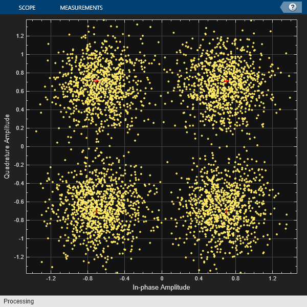
Initialize the constellation diagram object by using the comm.ConstellationDiagram System object to visualize how the constellation evolves as the synchronizers converge.
costellationobj = comm.ConstellationDiagram;         % Default view is for QPSK
if modScheme == "BPSK"
    costellationobj.ReferenceConstellation = [1, -1];
end
Processing Chain
To simulate the link-level chain and measure the BER of the CCSDS TM system, follow these steps.
Generate random bits to form a TF.
Generate the TM waveform by passing the TF through the
ccsdsTMWaveformGeneratorSystem object.Introduce RF impairments, such as CFO and sampling rate offset.
Add AWGN to the RF-impaired signal. This noisy signal is considered the received signal.
Pass the received signal through coarse frequency correction, which performs the initial coarse carrier frequency synchronization. Coarse frequency estimation is done using the "FFT-based" algorithm.
Perform carrier frequency and phase tracking by using the
comm.CarrierSynchronizerSystem object, which has a type 2 phase locked loop (PLL). This System object can track a stationary carrier frequency offset. The System object also introduces phase ambiguity, which is then removed by the frame synchronization module.Use a matched filter (root raised cosine filter) with the same configuration that is applied at the transmitter end. Because the symbol timing synchronization module works at a sampling rate that is higher than the symbol rate, the complex baseband samples are not down sampled to the symbol rate after filtering. It is down sampled such that at least 2 samples per symbol exist.
Perform symbol timing synchronization by using the Gardner timing error detector (TED) to remove the timing offset that is present in the signal.
Visualize the constellation after symbol timing and carrier frequency synchronization is complete. Observe how the constellation evolves over multiple iterations.
Demodulate the synchronized received signal and verify that the signal is at the symbol rate (that is, the samples per symbol is 1).
Perform frame synchronization and channel decoding to resolve the phase ambiguity, synchronize the frame to the start of the ASM, and then decode the synchronized frame to recover the TF.
numBitsForBER = 8; % For detecting which frame is synchronized
numMessagesInBlock = 2^numBitsForBER;
s = RandStream("mt19937ar","Seed",73);
for isnr = 1:numSNR
    reset(s);                            % Reset to get repeatable results
    nextSym = [];
    reset(bercalc);
    berinfo = bercalc(int8(1), int8(1)); % Initialize berinfo before BER is calculated
    tfidx = 1;
    numFramesLost = 0;
    prevdectfidx = 0;
    inputBuffer = zeros(numBitsInTF, 256,"int8");
    while((berinfo(2) < maxNumErrors) && ...
            (berinfo(3) < maxNumBits) && ...
            (numFramesLost < maxFramesLost))
        % Transmitter side processing
        bits = int8(randi(s,[0 1],numBitsInTF-numBitsForBER,1));
        % The first 8 bits correspond to the TF index modulo 256. When
        % synchronization modules are included, there can be a few frames
        % where synchronization is lost temporarily and then locks again.
        % In such cases, to calculate the BER, these 8 bits aid in
        % identifying which TF is decoded. If an error in these 8 bits
        % exists, then this error is detected by looking at the difference
        % between consecutive decoded bits. If an error is detected, then
        % that frame is considered lost. Even though the data link layer is
        % out of scope of this example, the data link layer has a similar
        % mechanism. In this example, only for calculating the BER, this
        % mechanism is adopted. The mechanism that is adopted in this
        % example is not as specified in the data link layer of the CCSDS
        % standard. And this mechanism is not specified in the physical
        % layer of the CCSDS standard.
        msg = [int2bit(mod(tfidx-1,numMessagesInBlock),numBitsForBER);bits];
        inputBuffer(:,mod(tfidx-1,numMessagesInBlock)+1) = msg;
        tx = tmWaveGen(msg);

        % Introduce RF impairments
        cfoInroduced = fqyoffsetobj(tx);                % Introduce CFO
        delayed = samplerateoffsetobj(cfoInroduced); % Introduce timing offset
        rxtemp = awgn(delayed, snr(isnr),'measured',s);  % Add AWGN

        numsym = length(cfoInroduced);
        [rx,nextSym] = buffer([nextSym;rxtemp],numsym);

        % Receiver-side processing
        coarseSynced = coarseFreqSync(rx);          % Coarse frequency synchronization
        normfSync = coarseSynced/rms(coarseSynced); % Normalize
        fineSynced = fineFreqSync(normfSync);       % Track frequency and phase
        filtered = rxfilter(fineSynced);            % Root raised cosine filter
        timeSynced = symsyncobj(filtered);          % Symbol timing synchronization
        timeSynced = timeSynced/rms(timeSynced);    % Normalize


        % Visualize constellation
        if showConstellation
            % Plot constellation of first 1000 symbols in a TF so
            % that variable size of fineSynced does not impede the
            % requirement of constant input size for the
            % comm.ConstellationDiagram System object.
            costellationobj(timeSynced);
        end

        demodData = demodobj(timeSynced); % Demodulate

        % Perform phase ambiguity resolution, frame synchronization, and channel decoding
        decoded = decoderobj(demodData);

        dectfidx = bit2int(decoded(1:8),8)+1;                % See the value of first 8 bits
        % Calculate BER and adjust all buffers accordingly
        if tfidx > 30 && ~isempty(decoded) % Consider to calculate BER only after 30 TFs are processed

            % As the value of first 8 bits is increased by one in each
            % iteration, if the difference between the current decoded
            % decimal value of first 8 bits is not equal to the previously
            % decoded one, then it indicates a frame loss.
            if dectfidx - prevdectfidx ~= 1
                numFramesLost = numFramesLost + 1;
                disp(['Frame lost at tfidx: ' num2str(tfidx) ...
                    '. Total frames lost: ' num2str(numFramesLost)]);
            else
                berinfo = bercalc(inputBuffer(:,dectfidx),decoded);
                if nnz(inputBuffer(:,dectfidx)-decoded)
                    disp(['Errors occurred at tfidx: ' num2str(tfidx) ...
                        '. Num errors: ' num2str(nnz(inputBuffer(:,dectfidx) - decoded))])
                end
            end
        end
        prevdectfidx = mod(dectfidx,numMessagesInBlock);
        % Update tfidx
        if ~isempty(decoded)
            tfidx = tfidx + 1;
        end
    end
    fprintf("\n");
    currentBer = berinfo(1);
    ber(isnr) = currentBer;
    disp(['Eb/N0: ' num2str(EbN0(isnr)) '. BER: ' num2str(currentBer) ...
        '. Num frames lost: ' num2str(numFramesLost)]);

    % Reset objects
    reset(tmWaveGen);
    reset(fqyoffsetobj);
    reset(samplerateoffsetobj);
    reset(coarseFreqSync);
    reset(rxfilter);
    reset(symsyncobj);
    reset(fineFreqSync);
    reset(demodobj);
    reset(decoderobj);
end
Errors occurred at tfidx: 31. Num errors: 149
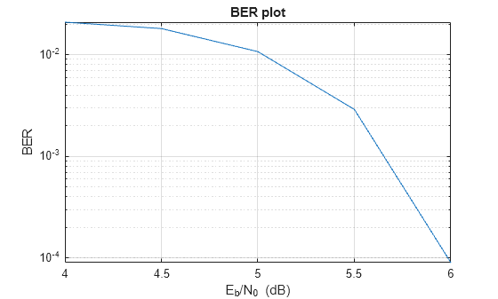
Eb/N0: 4. BER: 0.020877. Num frames lost: 0
Errors occurred at tfidx: 31. Num errors: 129
Eb/N0: 4.5. BER: 0.018075. Num frames lost: 0
Errors occurred at tfidx: 31. Num errors: 82
Frame lost at tfidx: 32. Total frames lost: 1
Frame lost at tfidx: 33. Total frames lost: 2
Errors occurred at tfidx: 34. Num errors: 71
Eb/N0: 5. BER: 0.01072. Num frames lost: 2
Errors occurred at tfidx: 31. Num errors: 20
Errors occurred at tfidx: 32. Num errors: 16
Errors occurred at tfidx: 33. Num errors: 20
Errors occurred at tfidx: 34. Num errors: 16
Errors occurred at tfidx: 35. Num errors: 19
Errors occurred at tfidx: 36. Num errors: 33
Eb/N0: 5.5. BER: 0.002896. Num frames lost: 0
Errors occurred at tfidx: 51. Num errors: 13
Errors occurred at tfidx: 52. Num errors: 16
Errors occurred at tfidx: 53. Num errors: 17
Errors occurred at tfidx: 84. Num errors: 15
Errors occurred at tfidx: 85. Num errors: 17
Errors occurred at tfidx: 143. Num errors: 13
Eb/N0: 6. BER: 9.0441e-05. Num frames lost: 0
Eb/N0: 6.5. BER: 0. Num frames lost: 0
Further Exploration
This example demonstrates BER simulation for convolutional codes with QPSK modulation in the presence of several RF impairments. To observe the link-level simulation chain for different scenarios, change the properties related to the channel coding and modulation schemes. The modulation schemes that are supported by the receiver in this example are BPSK, QPSK, and OQPSK. The channel coding schemes that are supported by the receiver in this example are none (that is, no channel coding), RS, convolutional, and concatenated codes.
Run a full BER simulation by setting the Eb/N0 value to 4:0.2:7 and observe the BER by setting maxNumBits to 1e8.
semilogy(EbN0,ber);
grid on;
xlabel('E_b/N_0 (dB)');
ylabel('BER');
title('BER plot');
Always reserve the initial few TFs for the symbol timing and carrier frequency synchronizers to lock. This example discards the first 30 TFs. This number can vary based on the SNR at which the receiver is operating and the parameters of the synchronization loops, such as loop bandwidth and damping factor. If you operate the receiver at low SNR and observe large errors in the initial values of tfidx, then the synchronizers are not yet locked. For the given simulation parameters, discard the initial TFs as appropriate. The second output arguments of comm.CoarseFrequencyCompensator and comm.CarrierSynchronizer System objects contain the information related to the estimated CFO, which can be used to assess whether the synchronization loops are locked or not.
Appendix
The example uses the following helper files:
References
[1] TM Synchronization and Channel Coding. Recommendation for Space Data System Standards, CCSDS 131.0-B-3. Blue Book. Issue 3. Washington, D.C.: CCSDS, September 2017.
[2] Radio Frequency and Modulation Systems--Part 1: Earth Stations and Spacecraft. Recommendation for Space Data System Standards, CCSDS 401.0-B-30. Blue Book. Issue 30. Washington, D.C.: CCSDS, February 2020.
[3] TM Synchronization and Channel Coding - Summary of Concept and Rationale. Report Concerning Space Data System Standards, CCSDS 130.1-G-3. Green Book. Issue 3. Washington, D.C.: CCSDS, June 2020.