NR NTN System Performance Evaluation with Transparent Payload LEO Satellite
R2026bThis example shows how to model a 5G New Radio (NR) non-terrestrial network (NTN) using a transparent payload low-Earth orbit (LEO) satellite in a system-level simulation. The example models a two-hop architecture where an NR base station (gNB) communicates with a set of user equipment (UE) nodes through a bent-pipe satellite relay. The NR protocol stack on the nodes includes radio link control (RLC), medium access control (MAC), and full physical layer (PHY) with NTN-specific adaptations for timing advance, Doppler pre-compensation, and extended hybrid automatic repeat request (HARQ) operation. You can evaluate how UE throughput and block error rate (BLER) vary with angular position within the satellite beam footprint and customize the orbital geometry, antenna configuration, and channel profile.
Transparent Payload NTN Architecture
NTN use satellite platforms to extend 5G NR coverage beyond the reach of terrestrial infrastructure. This example uses the transparent payload architecture defined in 3GPP TR 38.821, in which a LEO satellite relays radio frequency (RF) signals between a gNB and UE nodes without performing baseband processing. The gNB performs all baseband processing and hosts the NR protocol stack.
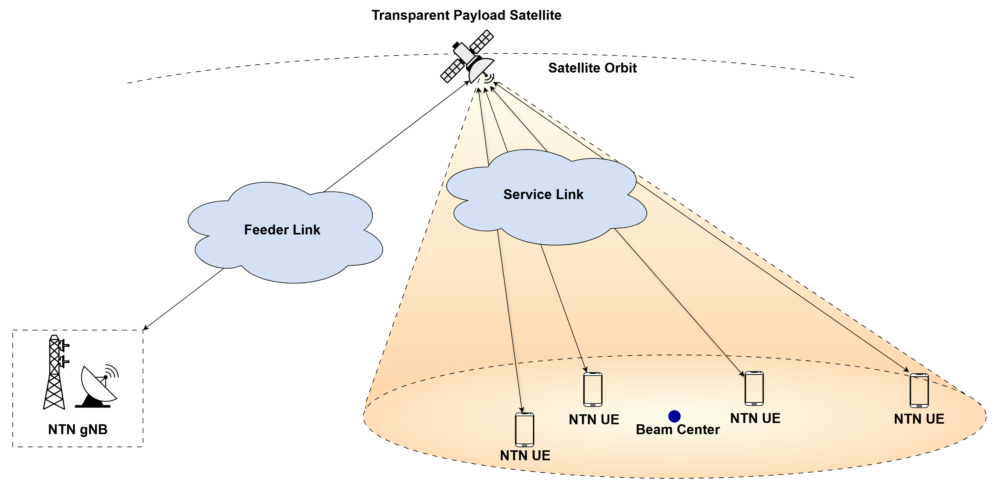
The scenario consists of three network node types:
gNB — Represents the co-located NTN gateway and 5G NTN base station as a single node. The gNB hosts the NR protocol stack, including the scheduler, RLC, MAC, and PHY layers, and uses a Ka-band dish antenna for the feeder link. The
helperNRNTNGNBhelper object represents the gNB.Satellite Remote Unit — Represents a transparent-payload LEO satellite operating as a bent-pipe relay. The satellite amplifies and frequency-translates RF signals between the feeder and service links without performing baseband processing. The
helperNRNTNRUhelper object represents the satellite remote unit.UE — Represents handheld user equipment communicating with the satellite over the S-band service link. The
helperNRNTNUEhelper object represents the UE.
This example demonstrates the following 3GPP NTN capabilities.
NTN Protocol Features
Timing advance management to compensate for the propagation delay.
Cell-specific K-offset to adjust HARQ feedback and uplink (UL) grant timing based on the satellite round-trip delay, as defined by the SIB19 NTN configuration.
Disabled downlink (DL) HARQ feedback to avoid waiting for acknowledgments over the long satellite round-trip delay.
Fixed repetitions to improve DL reliability when HARQ feedback is disabled.
Extended HARQ processing with up to 32 HARQ processes to sustain throughput over large round-trip delays.
Uplink synchronization validity timer as defined by the SIB19 NTN configuration.
Radio and Channel Features
A two-hop NTN channel consisting of a Ka-band feeder link between the gNB and satellite and an S-band service link between the satellite and UE.
3GPP TR 38.811 system channel model with environment-specific delay and angular characteristics for dense urban, urban, suburban, and rural deployments.
Free-space path loss and propagation-delay modeling on both feeder and service links.
Satellite antenna beam-gain modeling using a circular reflector with a Bessel radiation pattern and UE-specific gain based on angular offset from the beam center.
Bulk orbital Doppler pre-compensation applied at the gNB for the feeder link and the common service link up to the reference location and at the UE for the service link, with residual Doppler correction at each receiver.
System-Level Simulation Features
Configurable channel estimation using either perfect or practical estimation.
Frequency-division duplex (FDD) operation with full-buffer DL and UL traffic.
Per-UE coverage analysis that correlates angular position with throughput and BLER.
The example assumes that
The satellite and UEs positions remain static throughout the simulation.
The nodes send control packets out-of-band. A source node sends an out-of-band packet directly to the destination node, bypassing the channel and without consuming time-frequency resources. Control packets include buffer status report (BSR), DL assignment, UL grant, physical downlink shared channel (PDSCH) feedback, and csi report.
UE nodes are equipped with global navigation satellite system (GNSS) capabilities.
The example models propagation delay and Doppler effects only for in-band packets: physical uplink shared channel (PUSCH), physical downlink shared channel (PDSCH), channel state information reference signal (CSI-RS), and sounding reference signal (SRS).
The channel applies satellite Doppler only to the waveform as a carrier-phase ramp
exp(j*2*pi*fd*t), wheretrestarts from zero for each packet. The receiver removes orbital Doppler on a packet-relative grid, which aligns with this packet-relative Doppler phase.Irrespective of channel estimation technique, CSI measurements work based on perfect channel estimation.

Scenario Configuration
Create a wireless network simulator.
rng("default") % Reset the random number generator simDuration =0.5; % Simulation duration (in seconds) networkSimulator = wirelessNetworkSimulator.init(); % Initialize the network simulator
Configure the carrier frequencies for the feeder and service links of the transparent-payload satellite. The service link between the satellite and UEs operates in the S-band at approximately 2 GHz, which provides favorable propagation characteristics for handheld devices. The feeder link between the gNB and satellite operates in the Ka-band and uses high-gain dish antennas to support the long-distance backhaul connection. Ka-band operates on 27.5–30 GHz in UL and 17.7–20.2 GHz in DL. Assigning the feeder and service links to different frequency bands prevents self-interference within the satellite payload.
channelBandwidth = 5e6;       % Channel bandwidth (in Hz)
scs = 15;                     % Subcarrier spacing (in kHz)
serviceLinkULFreq = 2.275e9;  % Service link UL frequency (in Hz)
serviceLinkDLFreq = 2.525e9;  % Service link DL frequency (in Hz)
feederLinkULFreq  = 27.875e9; % Feeder link UL frequency (in Hz)
feederLinkDLFreq  = 19.95e9;  % Feeder link DL frequency (in Hz)
Create Satellite Scenario
Create a satellite scenario providing orbital mechanics, ground station geometry, and the visualization framework. The satellite orbits in a near-equatorial circular orbit at approximately 600 km altitude, positioned for high elevation angles over the Indian subcontinent coverage area.
numSlotsFrame = (10*scs)/15;
sampleDuration = (10/numSlotsFrame)*1e-3;                                      % Scenario time step = slot duration
startTime = datetime(2026,6,15,12,0,0);
sc = helperInitializeSatelliteScenario(startTime,simDuration,sampleDuration);

% Define a circular LEO orbit at approximately 600 km altitude (6371 km
% Earth radius + 600 km). The low inclination of 16° keeps the satellite
% near the equator for high elevation angles over the coverage area.
semiMajorAxis = 6971e3;
eccentricity = 0;
inclination = 16;
raan = 72;
argPeriapsis = 0;
trueAnomaly = 85;
sat = satellite(sc,semiMajorAxis,eccentricity,inclination,...
    raan,argPeriapsis,trueAnomaly,...
    OrbitPropagator="sgp4",Name="LEO-Satellite");
sat.Visual3DModel = "SmallSat.glb";
sat.Visual3DModelScale = 10000;
Create the gNB ground station at the Arvi Earth Station in Maharashtra, India, and place the UE ground stations on the Lakshadweep Islands, a remote region with no terrestrial 5G coverage. Position the UEs at increasing angular offsets from the satellite beam center to evaluate how throughput and BLER vary across the beam footprint and degrade toward the cell edge.
gwStation = groundStation(sc,18.20,73.86,Altitude=3,...
    Name="Gateway (Arvi)");

% UE positions: [latitude, longitude, altitude]
uePositions = [ ...
    10.5600,72.6550,0;                                    % UE1 (0.2° from beam center)
    10.5290,72.6400,0;                                    % UE2 (0.4° from beam center)
    10.5000,72.5600,0;                                    % UE3 (1.1° from beam center - beam edge)
    10.3295,72.8847, 0];                                  % UE4 (2.2° from beam center - beyond 3 dB edge)
numUEs = size(uePositions,1);
ueNames = "UE" + (1:numUEs);
ueStations = arrayfun(@(i) groundStation(sc,...
    uePositions(i,1),uePositions(i,2),...
    Altitude=uePositions(i,3),Name=ueNames(i)),1:numUEs);
Set Up Wireless Network
With the orbital and ground-station geometry defined in the satellite scenario, install NR protocol stack capabilities on each satellite scenario element to create the gNB, satellite remote unit, and UE network nodes.
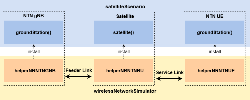
Create Satellite Remote Unit
Create a satellite remote unit as a bent-pipe relay with fixed transponder gains and high-power amplifier (HPA) saturation limits. The transponder applies a fixed electronic gain to the received signal on each path:
Forward link (gNB → Satellite → UE) —
TransponderGainForwardLink= 87 dB, clamped atServiceLinkTransmitPower= 46 dBmReturn link (UE → Satellite → gNB) —
TransponderGainReturnLink= 85 dB, clamped atFeederLinkTransmitPower= 30 dBm
The satellite uses two circular reflector antennas modeled according to section 6.4.1 of TR 38.811 using a Bessel radiation pattern. A 3 m dish provides service-link coverage for the UEs, while a 0.5 m dish forms the feeder link to the gNB.
serviceLinkAntenna = struct(Pattern="bessel",DishDiameter=3,ApertureEfficiency=0.65);
feederLinkAntenna = struct(Pattern="bessel",DishDiameter=0.5,ApertureEfficiency=0.65);

satelliteRU = helperNRNTNRU(sat, ...
    ServiceLinkTransmitPower=46, ...
    FeederLinkTransmitPower=30, ...
    TransponderGainForwardLink=87, ...
    TransponderGainReturnLink=85, ...
    ServiceLinkCarrierFrequency=[serviceLinkDLFreq,serviceLinkULFreq], ...
    FeederLinkCarrierFrequency=[feederLinkDLFreq,feederLinkULFreq], ...
    ServiceLinkAntenna=serviceLinkAntenna, ...
    FeederLinkAntenna=feederLinkAntenna, ...
    BeamVisualization="both");
Create gNB
Create a gNB with NTN-specific adaptations. The gNB disables DL HARQ feedback (DisableDLHARQFeedback) because the propagation delay can violate terrestrial HARQ timing relationships. A 2.4 m Ka-band dish antenna using a Bessel radiation pattern connects the gNB to the satellite over the feeder link. Configure the channel estimation method before creating the gNB.
channelEstMethod ="perfect"; gwAntenna = struct(Pattern="bessel",DishDiameter=2.4,ApertureEfficiency=0.65); gNB = helperNRNTNGNB(gwStation, ... ChannelBandwidth=channelBandwidth, ... SubcarrierSpacing=scs, ... TransmitPower=37, ... FeederLinkCarrierFrequency=[feederLinkDLFreq,feederLinkULFreq], ... ServiceLinkCarrierFrequency=[serviceLinkDLFreq,serviceLinkULFreq], ... NumHARQ=32, ... DisableDLHARQFeedback=true, ... NoiseFigure=3, ... GatewayAntenna=gwAntenna, ... ChannelEstimationType=channelEstMethod, ... ReceiverType="mmse");
To set the scheduler parameters, use the configureScheduler function. Set Scheduler to "RoundRobin", "ProportionalFair", or "BestCQI". Since DisableDLHARQFeedback is set to true, the scheduler performs repetitions controlled by NumRepetition. The scheduler uses the configured RVSequence values [0, 2, 3, 1] each DL transport block is transmitted once with RV=0 followed by NumRepetition repetitions with RV=2, 3, 1 spaced at fixed slot intervals, allowing the UE to combine soft bits for reliable decoding without feedback.
configureScheduler(gNB,Scheduler="RoundRobin",RVSequence=[0 2 3 1],NumRepetition=0);Create UE
Each UE represents a handheld terminal with a Class 3 transmit power of 23 dBm and a 0 dBi omnidirectional antenna. The UE communicates with the satellite over the S-band service link and computes timing advance using GNSS-derived position information and satellite ephemeris broadcast through SIB19.
ues = helperNRNTNUE.empty(0,numUEs);
for ueIdx = 1:numUEs
    ues(ueIdx) = helperNRNTNUE(ueStations(ueIdx), ...
        TransmitPower=23, ...
        NoiseFigure=7, ...
        ChannelEstimationType=channelEstMethod, ...
        ReceiverType="mmse");
end
Configure Connection
Establish the feeder link between the gNB and the satellite, and steer the satellite beam toward the beam-center location. The gNB broadcasts the SIB19 NTN configuration parameters that enable UEs to compute timing pre-compensation autonomously. This capability is essential in NTN deployments because the propagation delay of a LEO satellite greatly exceeds terrestrial NR timing tolerances.
The example configures these SIB19 NTN parameters.
ReferenceLocation — Defines the geographic reference point of the serving cell. UEs use this location together with GNSS position information to compute common timing advance.
CellSpecificKOffset — Defines the scheduling offset, in slots, that compensates for satellite round-trip delay in HARQ and downlink control information (DCI) timing relationships.
ULSyncValidityDuration — Specifies how long a UE can rely on its GNSS-derived timing advance before recalculating or validating the estimate. Unit is in seconds.
Finally, connect each UE to the gNB through the satellite and enable full-buffer traffic in both the DL and UL directions.
referenceLocation = [10.57 72.64 0];                                % Beam center [latitude,longitude,altitude] (Kavaratti,Lakshadweep)
cellSpecificKOffset = 12;                                           % Scheduling offset for NTN timing relationships (in slots)
ulSyncValidityDuration = 5;                                         % UL sync validity timer (SIB19) (in seconds)
gNB.connectRU(satelliteRU, ...
    ReferenceLocation=referenceLocation, ...
    CellSpecificKOffset=cellSpecificKOffset, ...
    ULSyncValidityDuration=ulSyncValidityDuration);
for ueIdx = 1:numUEs
    gNB.connectUE(ues(ueIdx),satelliteRU.ID,FullBufferTraffic="on");
end
addNodes(networkSimulator,gNB);
addNodes(networkSimulator,satelliteRU);
addNodes(networkSimulator,ues);
Configure Two-Hop Channel Model
Configure the NTN channel model using the h38811Channel single-link channel object for each link and the hNTNChannel two-hop channel adapter to compose them into the two-hop transparent payload path. The service link between the satellite and UE uses the frequency-selective fading model defined in TR 38.811, with delay and angular characteristics configured for a suburban environment, as defined in TR 38.811 Section 6.7.2. The feeder link between the gNB and satellite assumes a strong line-of-sight path because the Ka-band link uses high-gain dish antennas. As a result, the model does not apply fast fading. Both links apply propagation delay, free-space path loss, and bulk orbital Doppler shift to the waveform.
nrb = gNB.NumResourceBlocks;
waveformInfo = nrOFDMInfo(nrb,scs);

% Service link: S-band, frequency-selective TR 38.811 fading (Satellite <-> UE)
svcLink = h38811Channel(FadingType="FrequencySelective");
svcLink.SampleRate = waveformInfo.SampleRate;
svcLink.Environment = "Suburban";
svcLink.EnablePropagationLoss = true;
svcLink.EnableFreeSpacePathLoss = true;
svcLink.ApplySatelliteDoppler = true;

% Feeder link: Ka-band, no fast fading (gNB <-> Satellite)
fdrLink = h38811Channel(FadingType="None");
fdrLink.SampleRate = waveformInfo.SampleRate;
fdrLink.Environment = "Rural";
fdrLink.EnablePropagationLoss = true;
fdrLink.EnableFreeSpacePathLoss = true;
fdrLink.ApplySatelliteDoppler = true;

% Create two-hop adapter and register with simulator
ntnCh = hNTNChannel(gNB,satelliteRU,ues,svcLink,fdrLink);
addChannelModel(networkSimulator,@ntnCh.applyChannel);
Visualization and Log Traces
Logging of traces includes information that the example records for analysis after the simulation completes. Set the enableTraces flag to true to log the traces. Setting enableTraces to false will speed up the simulation.
enableTraces =  false;
Set up the scheduling logger.
if enableTraces
    numFrames = simDuration/0.01;
    simSchedulingLogger = helperNRSchedulingLogger(numFrames,gNB,ues);
end
Open the satellite scenario viewer to visualize the steered beam footprint on the surface of the Earth. The antenna radiation pattern from the helperNRNTNRU satellite remote unit object shows the service-link coverage area and gain rolloff relative to UE positions.
viewer = satelliteScenarioViewer(sc);
campos(viewer,uePositions(1,1),uePositions(1,2),3000000);
campitch(viewer,-70);
Set the number of updates per second for the metric plots.
numMetricPlotUpdates = 100;
Set up the metric visualizer.
metricsVisualizer = helperNRMetricsVisualizer(gNB,ues,...
    RefreshRate=numMetricPlotUpdates,...
    PlotSchedulerMetrics=true,...
    PlotPhyMetrics=true,...
    PlotCDFMetrics=false,ShowPeakDataRate=false);
By default, satelliteScenario advances its simulation clock automatically and precomputes satellite ephemeris, including satellite position and velocity over time. During simulation setup, helperNRNTNGNB, helperNRNTNUE, helperNRNTNRU, and h38811Channel helper objects query this ephemeris through latency and states to compute propagation delays and Doppler shifts. These helper objects cache the computed values and use them throughout the simulation. The wirelessNetworkSimulator controls simulation time and advances all network nodes. Therefore, to prevent satelliteScenario from advancing independently, set AutoSimulate to false to delegates time control to the wirelessNetworkSimulator. Apply this setting only after calling connectRU, connectUE, and creating the channel objects. When AutoSimulate is disabled, the scenario clears its ephemeris cache. Calling it earlier prevents the setup functions from accessing the ephemeris data required to compute propagation delays and Doppler shifts.
sc.AutoSimulate = false;
Simulation and Performance Analysis
Run the simulation for the specified simDuration.
run(networkSimulator,simDuration);
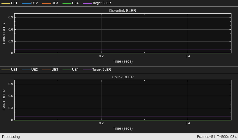
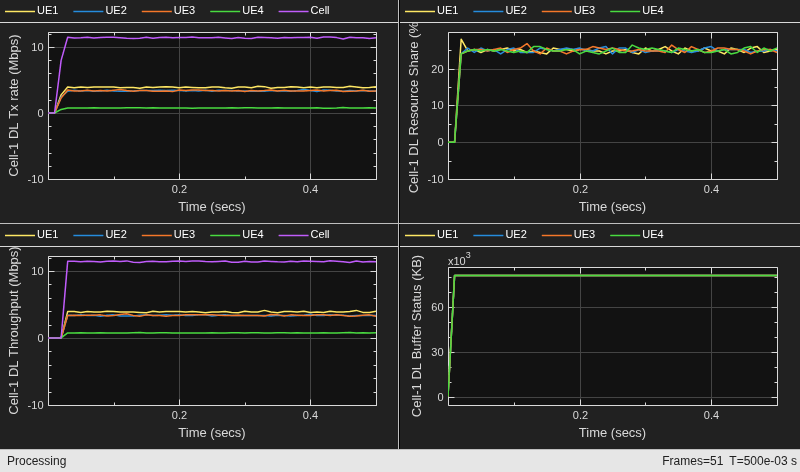
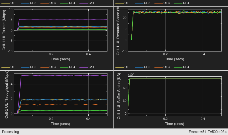
Display per-UE throughput, BLER, and spectral efficiency for both DL and UL directions of service link.
displayPerformanceIndicators(metricsVisualizer)
Peak UL throughput: 31.11 Mbps
Achieved cell UL throughput: 4.93 Mbps
Achieved UL throughput for each UE: [1.75        1.75        1.09        0.34]
Peak UL spectral efficiency: 6.22 bits/s/Hz
Achieved UL spectral efficiency for cell: 0.99 bits/s/Hz
Block error rate for each UE in the UL direction: [0  0  0  0]

Peak DL throughput: 31.11 Mbps
Achieved cell DL throughput: 10.95 Mbps
Achieved DL throughput for each UE: [3.74        3.23        3.24        0.73]
Peak DL spectral efficiency: 6.22 bits/s/Hz
Achieved DL spectral efficiency for cell: 2.19 bits/s/Hz
Block error rate for each UE in the DL direction: [0  0  0  0]
Correlate the geometric position of each UE within the satellite beam with achieved performance of throughput and BLER. UEs closer to the beam center receive higher antenna gain, while UEs farther from the beam center receive lower antenna gain, which reduces throughput and increases BLER near the cell edge.
beamCoverageMetrics = analyzeBeamCoveragePerformance(gNB,ues,simDuration, ...
    uePositions,referenceLocation,ueNames,semiMajorAxis)
beamCoverageMetrics = 4×7 table
UE Distance (km) Angle (deg) DL Throughput (Mbps) UL Throughput (Mbps) DL BLER UL BLER
_____ _____________ ___________ ____________________ ____________________ _______ _______
"UE1" 1.9833 0.18939 3.7375 1.7461 0 0
"UE2" 4.5641 0.43583 3.2343 1.7548 0 0
"UE3" 11.72 1.1191 3.2415 1.091 0 0
"UE4" 37.866 3.6111 0.73299 0.34008 0 0
Get insights using Copilot
The example also includes runtime visualizations of scheduling metrics and PHY metrics. For more information about the visualized metrics, refer to Simulation Visualizations (5G Toolbox).
Simulation Logs
The example saves the simulation logs in a MAT file for post-simulation analysis. For more information about the logged information, see the NR Cell Performance Evaluation with MIMO (5G Toolbox) example.
if enableTraces
    simulationLogs = cell(1,1);
    logInfo = struct(DLTimeStepLogs=[],ULTimeStepLogs=[], ...
        SchedulingAssignmentLogs=[]);
    [logInfo.DLTimeStepLogs,logInfo.ULTimeStepLogs] = getSchedulingLogs(simSchedulingLogger);
    logInfo.SchedulingAssignmentLogs = getGrantLogs(simSchedulingLogger);
    simulationLogs{1} = logInfo;
    save("simulationLogs","simulationLogs");
end
Further Exploration
Try running the example with these modifications.
Reduce
NumHARQ, for example to 16, to observe how a limited number of HARQ processes affects throughput over large satellite round-trip delays.Vary
CellSpecificKOffsetto study the tradeoff between HARQ timing alignment and scheduling efficiency. When you set it to a value which is very low, it causes HARQ timing violations. When you set it to a value which is very high, it ends up wasting scheduling opportunities.Increase
NumRepetitionto observe how PDSCH repetitions improve DL BLER at the cost of reduced spectral efficiency.Set
channelEstMethodtopracticalto evaluate how residual Doppler affects channel estimation and link performance.Increase
semiMajorAxis, for example to 7571e3 for an altitude of approximately 1200 km, to explore the tradeoff between coverage area, propagation delay, and Doppler shift.Enable atmospheric loss on the feeder link by setting
EnableAtmosphericLosstotrueand evaluate the impact of Ka-band rain attenuation.Increase the service-link antenna
DishDiameter, for example to 4 m, to improve antenna gain and observe how a narrower beam affects beam-edge coverage.Move the UEs closer to or farther from the beam center and evaluate how antenna gain affects throughput and BLER across the coverage area.
Supporting Files
The example uses these supporting files.
helperNRNTNRU: Implements the transparent payload satellite remote unithelperNRNTNGNB: Implements the NTN-adapted gNBhelperNRNTNUE: Implements the NTN-adapted UEh38811Channel: Implements the TR 38.811 NTN channel model for a single linkhNTNChannel: Composes twoh38811Channelobjects into the two-hop transparent relay pathhNTNBesselElement: Implements Parabolic reflector antenna elementhelperInitializeSatelliteScenario: Creates and configures the satellite scenariohelperNRNTNSatelliteMobility: Implements satellite orbital position updateshelperNRNTNGNBMAC: Implements the gNB MAC layerhelperNRNTNUEMAC: Implements the UE MAC layerhelperNRNTNScheduler: Implements the NTN scheduler with repetition managementhelperNRNTNGNBFullPHY: Implements the gNB physical layerhelperNRNTNUEFullPHY: Implements the UE physical layerhelperNRNTNRUPHY: Implements the satellite physical layer with fixed-gain amplification and frequency conversionhelperNRNTNBase: Provides base class with satellite scenario node association for NTN nodeshelperNRNTNPHYBase: Provides PHY utilities for Doppler frequency offset application and path filter correctionhelperNRNTNEventBuffer: Implements symbol-level event buffering for time-based action schedulinghelperNRNTNSLSUtilities: Provides static utilities for timing advance and slot offset calculationshelperNRSchedulingLogger: Implements scheduling information logging functionalityhelperNRMetricsVisualizer: Implements metrics visualization functionalityhelperPlotECDF: Plots empirical cumulative distribution function curves for performance metricshNRKPIManager: Calculate 5G NR Key Performance Indicators
Local Functions
function beamCoverageMetrics = analyzeBeamCoveragePerformance(gNB,ues,simDuration,uePositions,beamCenter,ueNames,semiMajorAxis)
%analyzeBeamCoveragePerformance Correlate UE beam position with achieved performance
earthRadius = 6371e3;
satAltitudeKm = (semiMajorAxis - earthRadius)/1e3;
kmPerDegLat = 111.32;
kmPerDegLon = 111.32*cosd(beamCenter(1));
numUEs = numel(ues);
gnbStats = statistics(gNB,"all");
gnbMACDst = gnbStats.MAC.Destinations;
gnbPHYDst = gnbStats.PHY.Destinations;
distKm = zeros(numUEs,1);
angleDeg = zeros(numUEs,1);
dlTputMbps = zeros(numUEs,1);
ulTputMbps = zeros(numUEs,1);
dlBLER = zeros(numUEs,1);
ulBLER = zeros(numUEs,1);
for i = 1:numUEs
    dLat = (uePositions(i,1) - beamCenter(1))*kmPerDegLat;
    dLon = (uePositions(i,2) - beamCenter(2))*kmPerDegLon;
    distKm(i) = sqrt(dLat^2 + dLon^2);
    angleDeg(i) = atand(distKm(i)/satAltitudeKm);
    rnti = ues(i).RNTI;
    ueStats = statistics(ues(i));
    dlTputMbps(i) = ueStats.MAC.ReceivedBytes*8/(simDuration*1e6);
    ulTputMbps(i) = gnbMACDst(rnti).ReceivedBytes*8/(simDuration*1e6);
    phyStats = ueStats.PHY;
    if phyStats.ReceivedPackets > 0
        dlBLER(i) = phyStats.DecodeFailures/phyStats.ReceivedPackets;
    end
    ulPhyStats = gnbPHYDst(rnti);
    if ulPhyStats.ReceivedPackets > 0
        ulBLER(i) = ulPhyStats.DecodeFailures/ulPhyStats.ReceivedPackets;
    end
end
beamCoverageMetrics = table(ueNames',distKm,angleDeg,dlTputMbps,ulTputMbps,dlBLER,ulBLER,...
    VariableNames=["UE" "Distance (km)" "Angle (deg)" "DL Throughput (Mbps)" ...
    "UL Throughput (Mbps)" "DL BLER" "UL BLER"]);
end
See Also
Objects
satelliteScenarioViewer|nrScheduler(5G Toolbox)

