fircls1
Constrained-least-squares linear-phase FIR lowpass and highpass filter design
Syntax
Description
Examples
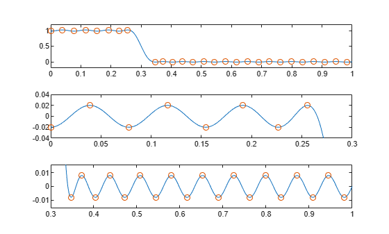
Design a 55th-order lowpass filter with normalized cutoff frequency rad/sample. Specify a passband ripple of 0.02 and a stopband ripple of 0.008. Display plots of the bands. The bound violations denote the iterations of the procedure as the design converges.
n = 55;
wo = 0.3;
dp = 0.02;
ds = 0.008;
b = fircls1(n,wo,dp,ds,"both");
Bound Violation = 0.0870385343920
Bound Violation = 0.0149343456540
Bound Violation = 0.0056513587932
Bound Violation = 0.0001056264205
Bound Violation = 0.0000967624352
Bound Violation = 0.0000000226538
Bound Violation = 0.0000000000038
Input Arguments
Output Arguments
Algorithms
The fircls1 function uses an iterative least-squares algorithm to
obtain an equiripple response. The algorithm is a multiple exchange algorithm that uses
Lagrange multipliers and Kuhn-Tucker conditions on each iteration.
References
[1] Selesnick, I. W., M. Lang, and C. S. Burrus. “Constrained Least Square Design of FIR Filters without Specified Transition Bands.” Proceedings of the 1995 International Conference on Acoustics, Speech, and Signal Processing. Vol. 2, 1995, pp. 1260–1263.
[2] Selesnick, I. W., M. Lang, and C. S. Burrus. “Constrained Least Square Design of FIR Filters without Specified Transition Bands.” IEEE® Transactions on Signal Processing. Vol. 44, Number 8, 1996, pp. 1879–1892.