New Simulink context menus prioritize frequently used functionality
In R2026a, the context menus that appear when you right-click the Simulink® model canvas or model elements such as blocks, signal lines, and annotations are changing. This image shows the differences between the context menu that opens when you right-click a Constant block in R2025b and the context menu that opens when you right-click the same block in R2026a.
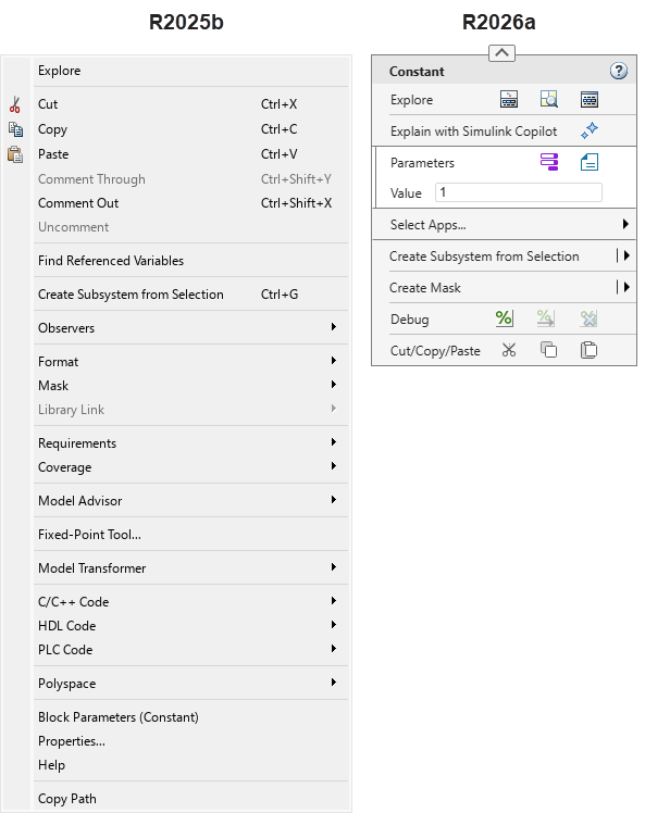
In addition to conventional menu items, the R2026a context menu design includes interactive elements such as buttons, text boxes, radio buttons, check boxes, and drop-down lists. To view a tooltip that describes the action you can take by pressing a button, pause your pointer on the button icon.
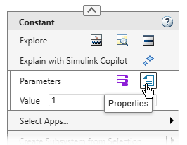
This table lists some of the common buttons in the context menus of blocks.
| Button | Tooltip |
|---|---|
| Model Data Editor | |
| Referenced Variables | |
| Open in Model Explorer | |
| Explain with Simulink Copilot | |
| Block Parameters | |
| Properties | |
| Comment out the block. | |
| Comment through the block. | |
| Uncomment the block. | |
| Cut | |
| Copy | |
| Paste |
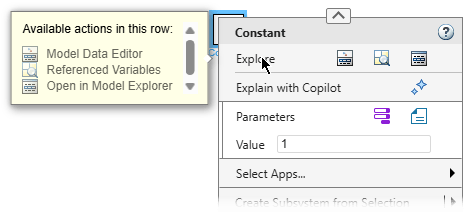
For a tooltip showing a list of all the actions that you can take by pressing the buttons in a button row, click the name of the button row. For each button, the tooltip shows the button icon followed by a description of the button action. When there is only one button in a button row, clicking the name of the button row presses the button instead of opening a tooltip.
To open the help documentation, in the upper right corner of the context menu, click the
Open help documentation button
.
You can find formatting options in the format bar, for example, options to change fonts
and colors, show or hide block names, show or hide the content preview of a subsystem, and
auto-arrange the model. You can also find clipboard options such as copy and paste there. To
expand or collapse the format bar, click the arrow button
at the top of the context menu.

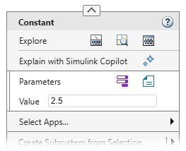
You can set the values of certain parameters and properties directly in the context menu using text boxes, radio buttons, check boxes, and drop-down lists. For example, to set the value of a Constant block, right-click the block, and in the Value box, enter the new value.
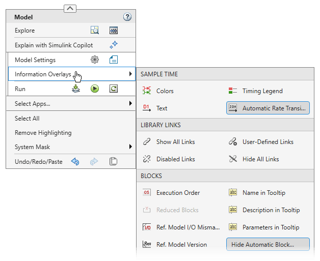
To add information overlays such as units or execution order to a model, right-click the model canvas and pause your pointer on Information Overlays. Then, select an overlay option.
In R2025b, you could access options that belong to an app such as the HDL Coder™ app or the Polyspace® Code Verifier app through menu items such as HDL Code or Polyspace. In R2026a, app-specific options are located in app sections. App sections are not shown by default. To access app-specific options, you must add the relevant app section to the context menu.
For example, this image highlights the options in the R2025b Constant block context menu that you can access in R2026a by adding app sections.
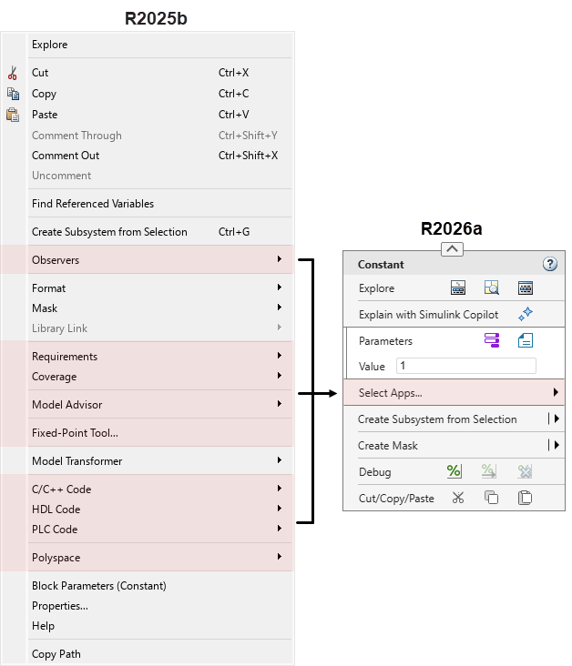
To add an app section to the context menu, pause your pointer on Select Apps, and then select the app. When you add an app section, the same app windows and toolstrip tabs open as when you click the app icon on the Apps tab in the Simulink Toolstrip. Alternatively, open the app from the Simulink Toolstrip. When you open an app, the corresponding app section appears in the context menu.

If you are unsure whether a menu option you use is part of an app, or you know the option is part of an app but are unsure of which app, check this table. The table lists the apps associated with some of the most common R2025b context menu items.
| R2025b Context Menu Item | App |
|---|---|
| C/C++ Code | |
| Coverage | |
| Design Verifier | |
| Fixed-Point Tool | |
| HDL Code |
|
| Identify Modeling Clones | |
| Linear Analysis Points | |
| Metrics Dashboard | The options for this app are no longer available in the context menu. |
| Model Advisor | |
| Model Slicer | |
| Model Transformer | The options for this app are no longer available in the context menu. |
| Observers | |
| PLC Code | |
| Polyspace |
|
| Requirements or Requirements at This Level | |
| Test Harness |
|
You can add multiple app sections. To add another app section, pause your pointer on Select Apps again, and select a different app.
In the model in which you add an app section, the app section appears in all context menus and persists across Simulink sessions. For example, if you right-click a block and add an app section, and then right-click a signal line in the same model, the signal line context menu also shows the app section you added. However, if you open a context menu in a different model, the context menu does not show the app section. If you open a context menu when none of the actions of an app section are available, the context menu might not show the app section.
To collapse an app section, click the down arrow button
in the upper left of the app section. To expand the app
menu section, click the arrow again.
To remove an app section from the context menu, pause your pointer on the app icon at the left edge of the app-specific section and click Close App. Alternatively, pause your pointer on Select Apps, and then cancel the app selection. You can also collapse the app section and then click the X on the right.
In addition to adding and removing app sections, you can also customize the context menus with the new design by adding widgets or disabling widget actions. For information, see Customize Simulink Context Menu Using Extension Points.
For lookup tables showing how you can access R2025b context menu options in R2026a, see Find Simulink Context Menu Options. The tables cover the options in the context menus of Constant blocks, top level models, signal lines, and text annotations. For a list of options that are no longer available in the Simulink context menus going forward, see Options that have been removed from Simulink context menus.
Move blocks in and out of subsystems using Simulink Toolstrip
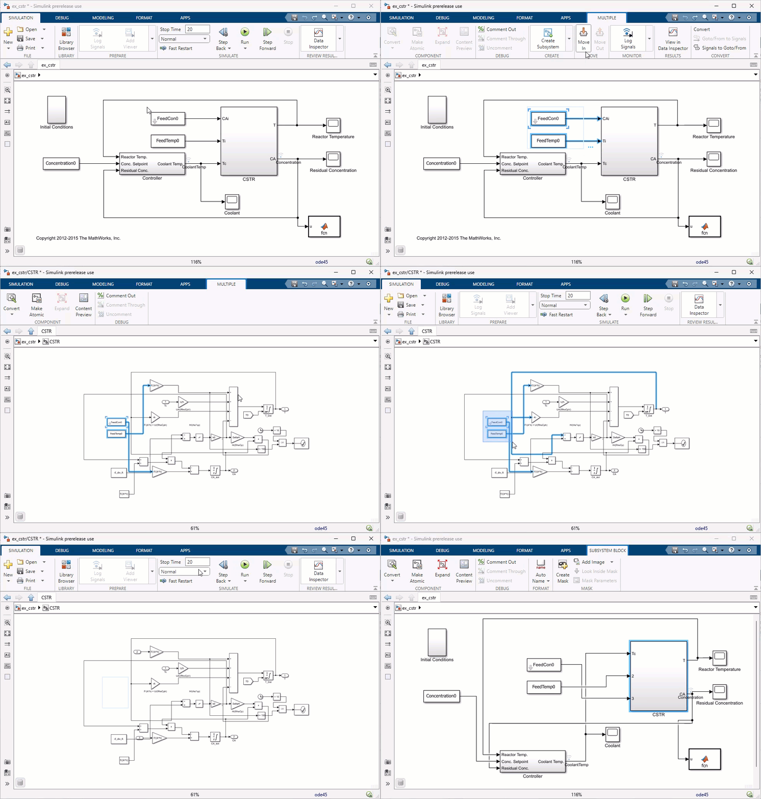
Starting in R2026a, when you select multiple blocks on the Simulink canvas, you can use the Move In and Move Out buttons on the Simulink Toolstrip to move the blocks into or out of a subsystem. If the selected blocks are connected to a subsystem, use the Move In button to move the blocks into the subsystem. If the selected blocks are inside a subsystem, use the Move Out button to move the blocks up one level from the subsystem. This allows you to reorganize the model while preserving signal connections and block properties after refactoring. This feature eliminates the need to manually move blocks in or out of the subsystem when required.
The Move In and Move Out buttons appear in the Move section of the Multiple tab of the Simulink Toolstrip. Alternatively, you can use the context menu for move operations. Right-click the selected blocks and select Move > Move In to move blocks into a subsystem, or Move > Move Out to move blocks up one level. You can undo (Ctrl+Z) and redo (Ctrl+Y) the move operation to reverse or restore any changes.
For more information, see Move Blocks Into and Out of Subsystems.
The Simulink Environment: Self-paced, interactive course available as part of Online Training Suite subscription
The Simulink Environment is a new course that teaches you to:
Use block diagrams and MATLAB® code to model and simulate algorithms.
Configure how models run using callbacks.
Visualize simulation outcomes.
Manage simulation data and exchange data with Simulink.
For more information, see The Simulink Environment.
Model Dynamic Systems: Self-paced, interactive course available as part of Online Training Suite subscription
Model Dynamic Systems is a new course that teaches you to:
Model continuous and discrete dynamic systems from mathematical models using differential and difference equations, transfer functions, and state-space representations.
Represent physical boundaries and multiple sample rates.
For more information, see Model Dynamic Systems.
Access course readings, videos, and quizzes without product licenses
You can now open a course even if you do not have licenses for all products used by the course. Learning activities such as readings, videos, and quizzes no longer require a product license. To open a Simulink exercise, you must have licenses for all products used by the exercise.
For more information, see Simulink Online Courses.
Save copy of model from the Simulink Editor
You can now save a copy of your model from the Simulink Editor. On the Simulation tab, select Save > Save Copy As. When you use this option, Simulink saves the copy of the file in the specified folder, but it does not replace the model in your current session.
Simulink Preferences has been renamed Simulink Settings
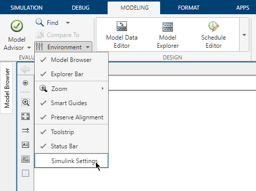
Simulink Preferences has been renamed Simulink Settings. Use Simulink Settings to specify Simulink editing environment options and default behaviors. To open Simulink Settings, in the Simulink Toolstrip, on the Modeling tab, in the Evaluate and Manage section, select Environment > Simulink Settings.
Model Finder: Added support to share and reuse model databases for team collaboration
Previously, to share a Model Finder database, you had to
share the database file with team members, who would then manually import it in their
settings folder using the Model Finder user interface (UI). Starting in R2026a, you can
directly share and reuse model databases by using a shared repository and customizing the
Model Finder UI with the MATLAB
sl_customization function. By registering the customizations
programmatically, you only need to do a one-time setup to access shared databases.
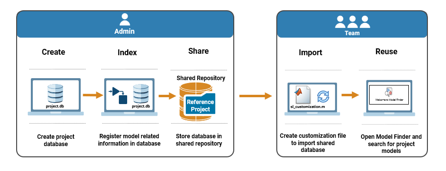
To set up a shared database, use Model Finder to create a database containing information of project related Simulink models. Store this database in a shared repository, such as a file server, cloud storage, or source code management (SCM) system.
To access the shared database, team members have to specify a customization to import the
database to their Model Finder in the sl_customization.m file. After
importing, the shared database appears in the Model Finder UI, and team members can search
for models in the database.
To import the shared database wireless_systems.db from a shared
repository and assign it the alias Shared Database, specify this
customization in the customization file. Use the ModelFinderCustomizer class
function on the customization manager object cm to specify the
customization.
function sl_customization(cm) dbPath = fullfile("simulink","modelfinderdatabases","wireless_systems.db"); cm.ModelFinderCustomizer.importDatabase(dbPath,“Shared Database”); end
For more information, see Configure, Share, and Search Databases.
Change to default equation font
Starting in R2026a, equations on the Simulink canvas might display a modified default font due to an upgraded equation rendering engine. Additionally, on the Windows® operating system, user interface elements such as the Property Inspector now use the Windows system font, by default.
Functionality being removed or changed
Simulink Fundamentals course will be discontinued
Warns
The Simulink Fundamentals course will be discontinued. You will be unable to start or continue this course after it is discontinued. Course progress and certificates will still be available.
To develop a broad skill set across core Simulink functionality, take these new courses instead:
These new courses provide the same material and more.
Options that have been removed from Simulink context menus
In R2026a, the context menus that appear when you right-click the Simulink model canvas or model elements such as blocks, signal lines, and annotations are changing. To maximize the compactness of the new context menus and the convenience of accessing frequently used options, some options have been removed from the context menus. The tables list some of these options and alternative ways to take the associated actions.
Block Context Menu
| R2025b Context Menu Action | Action in R2026a |
|---|---|
| Right-click the block and select Find Referenced Variables. | Navigate into the model or component whose referenced variables you
want to find. Right-click the canvas, and then click the Referenced
Variables button |
| Right-click the block and select Format > Flip Block Name. | Select the block. In the Simulink Toolstrip, on the Format tab, click Flip Name. |
| Right-click the block and select Format > Fit to Content. | Select the block. In the Simulink Toolstrip, on the Format tab, click Fit to Content. |
Right-click any type of block representing a subsystem, for example an If Action Subsystem block, and select one of these options:
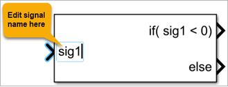
| Select any type of block representing a subsystem, for example an If Action Subsystem block. In the Simulink Toolstrip, on the Format tab, in the Ports section, click the Port Labels button and select one of these options:
|
| Right-click the block and select Format > Bring to Front. | Select the block. In the Simulink Toolstrip, on the Format tab, click the
Bring to front button |
| Right-click the block and select Format > Send to Back. | Select the block. In the Simulink Toolstrip, on the Format tab, click the
Send to back button |
Top Model Canvas Context Menu
| R2025b Context Menu Action | Action in R2026a |
|---|---|
| Right-click the model canvas and select Sample Time > All. | Right-click the model canvas and select Information Overlays. Then, select all overlays under Sample Time. |
| Right-click the model canvas and select Sample Time > Off. | Right-click the model canvas and select Information Overlays. Then, clear all overlays under Sample Time |
Right-click the model canvas and set Animation
Speed to Fast,
Medium, Slow, or
None. | In the Simulink Toolstrip, on the Debug tab, set
Animation speed to Fast,
Medium, Slow, or
None. |
Annotation Context Menu
| R2025b Context Menu Action | Action in R2026a |
|---|---|
| Right-click the annotation and select Format > Bring to Front. | Select the annotation. In the Simulink Toolstrip, on the Format tab, click the
Bring to front button |
| Right-click the annotation and select Format > Send to Back. | Select the annotation. In the Simulink Toolstrip, on the Format tab, click the
Send to back button |
Right-click the annotation and select one of these options:
| Right-click the annotation, and then click the Properties button
|
| Right-click the annotation and select Enable Tex Commands. | Right-click the annotation, and then click the Properties button
|
| Right-click the annotation and select Show in Library Browser. | Select the annotation. In the Simulink Toolstrip, on the Library tab, click Show Annotations in Library Browser. |
Get extension point, action, and icon names of Simulink Context Menu widgets and Simulink Toolstrip widgets using slUIDeveloperMode
function
Still runs
You can customize the Simulink Context Menu and the Simulink Toolstrip. For example, you can add your own custom toolstrip tabs and context menu items. The context menu and toolstrip are comprised of widgets. To reuse the action or icon of an existing widget for a custom widget, you need to know the name of that action or icon. To add context menu widgets, you need to know the names of extension points — predefined locations at which you can add widgets.
You can get the names of actions, icons, and extension points by entering developer mode, pausing your pointer on a widget, and pressing Ctrl (command ⌘ on macOS). The MATLAB Command Window outputs the action, icon, and extension point names for the widget.
In previous releases, you could only enter developer mode using the slToolstripDeveloperMode function. Starting in R2026a, you can also enter
developer mode using the slUIDeveloperMode function.
slUIDeveloperMode("on")The slToolstripDeveloperMode function will be removed in a future
release.
For information about customizing the Simulink Context Menu, see Customize Simulink Context Menu Using Extension Points. For information about customizing the Simulink Toolstrip, see Create Custom Simulink Toolstrip Tabs.
Model Finder function updates
These Model Finder functions have been renamed:
The modelfinder.setDefaultDatabase function is now
renamed to modelfinder.setDatabaseToIndex.
The modelfinder.setSearchDatabase function is now renamed
to modelfinder.setDatabaseForSearch.
Run Multiple Simulations in Parallel: Self-paced, interactive course available as part of Online Training Suite subscription
Run Multiple Simulations in Parallel is a new course that teaches you to:
Run multiple simulations of a Simulink model in parallel using the parsim
function.
Perform post-simulation computations on simulation data.
Monitor simulations and visualize simulation data in the Simulation Manager.
For more information, see Run Multiple Simulations in Parallel.
Configure Simulink Solvers to Improve Performance: Self-paced, interactive course available as part of Online Training Suite subscription
Configure Simulink Solvers to Improve Performance is a new course that teaches you to:
Configure the Simulink solver settings to gain finer control of simulation accuracy and optimize simulation speed.
Troubleshoot common simulation performance issues such as model stiffness and algebraic loops.
For more information, see Configure Simulink Solvers to Improve Performance.
Faster rapid accelerator simulations
Starting in R2026a, rapid accelerator mode introduces a persistent server that keeps libraries loaded between simulation runs. Keeping libraries in memory reduces the total simulation time by about 1.1 seconds for subsequent simulations. The improvement is most noticeable for smaller models with shorter simulation times, where library loading represents a larger portion of the total simulation time.
To measure this improvement, the following code was used in both R2025b and R2026a. The first simulation builds the rapid accelerator simulation target and loads the necessary libraries. In R2026a, when the simulation ends, the libraries remain in memory. The second simulation can then run without the overhead of loading these libraries. To compare total simulation times across releases, check the total elapsed wall time reported for the second simulation, which is in the simulation metadata.
mdl = "vdp"; openExample("simulink_general/VanDerPolOscillatorExample",SupportingFile=mdl) out1 = sim(mdl,SimulationMode="rapid-accelerator"); out2 = sim(mdl,SimulationMode="rapid-accelerator",RapidAcceleratorUpToDateCheck="off"); t = out2.SimulationMetadata.TimingInfo.TotalElapsedWallTime;
The approximate times for the second simulation are
R2025b: 2.3s
R2026a: 1.2s
The code was timed on a Windows 10, AMD Ryzen 5 PRO 5650U @ 2.30 GHz test system.
Simulate models with algebraic loops faster by using rapid accelerator mode
You can now simulate models that contain algebraic loops using rapid accelerator mode and in applications deployed using Simulink Compiler™. In previous releases, you could use only normal or accelerator mode to simulate models that contain algebraic loops. Rapid accelerator mode provides the fastest execution time by generating a simulation target that runs in a separate process. For more information, see How Acceleration Modes Work.
Apply time tolerance to external input data
When you load external input data for simulations, many input data formats require that you specify both time and data values to define the input. At each time step in the simulation, the block that loads the data determines the output value to provide to the simulation by comparing the current simulation time with the timestamps in the external input data. To control whether the software applies a tolerance when performing this comparison, use the new Input time tolerance model configuration parameter.
With this parameter enabled, the software considers the timestamp in the external input
data and the simulation time equal if the timestamp is within 128*eps(t)
of the simulation time t. You cannot modify the value of the time
tolerance. The time tolerance applies to all external input data loaded using any of these
blocks:
Top-level In Bus Element block
Top-level Inport block
The Input time tolerance parameter is supported in all simulation modes, simulations deployed using Simulink Compiler, and production code generation.
Load external input data that contains Inf or NaN
values
You can now load external input data that contains Inf and
NaN data values using any of these blocks:
Top-level In Bus Element block
Top-level Inport block
Signal Editor block
From Workspace block
From File block
For example, to evaluate the system response to unexpected values, you can load external
input data that contains one or more Inf or NaN
values.
In previous releases, the software issued an error if external input data loaded using
these blocks contained any Inf or NaN values.
Configure nontunable parameter values for fast restart simulations using the Simulation object
You can now use the Simulation object to configure nontunable parameter values for fast restart simulations.
You must specify the nontunable parameter values on the Simulation object before initializing or running the first fast restart simulation.
Once initialized in fast restart, you cannot modify nontunable parameter values.
Nontunable parameter values are not reverted in the model until you terminate the simulation or disable fast restart.
Previously, you could not specify nontunable parameter values on Simulation objects used to run fast restart simulations. To specify a nontunable parameter value, you had to modify the parameter value in the model before running the first fast restart simulation.
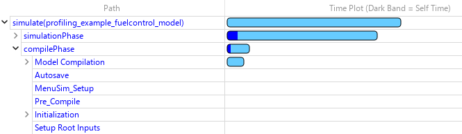
Analyze distribution of compilation time using the Simulink Profiler
The Simulink Profiler now provides information about how compilation time is distributed among compilation phases and among referenced models that simulate in normal mode. To view the compilation information, use one of these approaches:
In the Simulink Profiler, in the Profiler Report pane, click Show
Execution Stack View
. Then, expand the simulate
and compilePhase nodes.
Inspect the rootExecNode property of the Simulink.profiler.Data object returned with the results of the
profiling simulation.
In previous releases, the Simulink Profiler provided only the total time required to compile the model.
Debug models using Model Slicer at breakpoints
Starting in R2026a, you can launch Model Slicer directly from the Breakpoints List when your Simulink model pauses at a breakpoint. This integration allows you to trace the signal values back to their sources so you can isolate the root cause of unexpected behavior in large models. A Simulink Check™ license is required to launch Model Slicer from the Breakpoints List.
In the Breakpoints List, Model Slicer:
Sets the starting point to the signal associated with the current breakpoint.
Updates the slice criteria to match the selected breakpoint when you add a new breakpoint or switch between existing breakpoints.
When model simulation hits a breakpoint, perform these steps to use Model Slicer from the Breakpoints List:
On the Debug tab, click Breakpoints List. The Breakpoints List opens at the bottom of the Simulink Editor.
In the Breakpoints List, click the Debug using Slicer button
to debug the signal. You can also:
Add a starting point by clicking the Add Starting Point button
.
View the upstream and downstream flow of the signals in the model
using
button.
Click the Close Model Slicer button
to close the Model Slicer.
For more information, see Breakpoints List and Trace Faulty Signal Paths Using Model Slicer at Signal Breakpoints (Simulink Check).
Improved support for breakpoints in accelerator mode
The Pause within time step option in the Breakpoints List now affects the behavior of breakpoints only in normal mode simulations. Supported breakpoints pause between time steps in accelerator mode simulations even if Pause within time step is selected. Previously, breakpoints were not supported in accelerator mode simulations if Pause within time step was selected.
Accelerator mode still does not support some breakpoints that normal mode supports. For example, breakpoints inside model references are not supported in accelerator mode.
The software now indicates which breakpoints are supported in accelerator mode by dimming unsupported breakpoints in the block diagram and the Breakpoints List. Previously, unsupported breakpoints appeared active during accelerator mode simulations but did not pause the simulation.
Selectively load signal data from an MLDATX file to the workspace
Starting in R2026a, you can inspect, filter, and load a subset of signals from an MLDATX
file to the workspace by creating an mldatx.io.File object that references data in the MLDATX file. These
operations do not require Simulink.
To access data in an MLDATX file, use mldatxfile
to create an mldatx.io.File object. This object references signal data and
metadata for runs saved in the file. Use the object to selectively load signals into the
workspace.
Filter and export data with these functions:
getSignals — Filter signals based on criteria such as signal
name, logging domain, or run index.
load — Export a subset of data from the MLDATX file to the
workspace.
Inspect signal and run information with these functions:
getRunCount — Get the number of runs saved in the MLDATX
file.
getRunInfoByIndex — Get detailed metadata for a run saved in
the MLDATX file.
listRuns — Return a summary table of runs saved in the
MLDATX file with columns for the run index, run name, creation date, and the
name of the model that generated the run.
listSignals — Return a summary table of signals saved in the
MLDATX file with columns for the signal name, run index, logging domain,
block path, block sub-path, and port index.
To access data for an individual signal in an MLDATX file, use
getSignals to create an mldatx.io.Signal object. This object references signal data and metadata for a
signal saved in the MLDATX file and referenced by the mldatx.io.File
object. Use the object to selectively inspect signal metadata and load data for a specific
signal to the workspace using the load function.
When data is too large to fit into memory, use the getAsDatastore function to create a matlab.io.datastore.MLDATXSignalDatastore object to load the data into the
workspace incrementally.
Live stream data to XY visualizations
Live streaming of data to XY visualizations in the Simulation Data Inspector, Record
block, and XY Graph block is supported again. Such live streaming was supported in R2024b
and earlier, but was not supported in R2025a. To live stream data to an XY visualization,
data must be plotted as a scatter plot. To change the line style to only data markers, click
Visualization Settings
and in the Axes section, select
Markers and clear Line. Trend lines are not
supported while live streaming XY data.
Export data from the Simulation Data Inspector to a Parquet file
You can now export scalar and multidimensional signals from the Simulation Data Inspector
to a Parquet file. The Simulation Data Inspector can export real and complex data of any
built-in data type, as well as enumerations, strings, fixed-point data, buses, and arrays of
buses. The Simulation Data Inspector can also export messages to a Parquet file as
double values. When exporting to a Parquet file, you can configure
shared or individual time columns, set row groups by height or size, and choose the
compression used when saving the file.
Get and set data access for MATLAB callback functions programmatically
Programmatically configure and retrieve data access settings that enable streaming of
signal data to a MATLAB callback function during simulation using the new Simulink.sdi.setDataAccess and Simulink.sdi.getDataAccess functions.
Get storage size of signals logged to the Simulation Data Inspector
You can now view the approximate storage size of data logged to the Simulation Data Inspector when a simulation is paused or stopped.
To interactively access storage size information, you can:
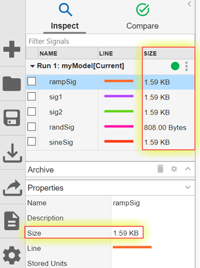
Add the Size column to the signal table in either the Inspect or Compare pane to display a specific property for all logged signals in the table.
View metadata for a signal, run, or comparison in the new Size row of the Properties pane.
For more information, see Inspect Signal, Run, and Comparison Metadata.
To programmatically access storage size information, you can:
Use the new NumBytes property of a Simulink.sdi.Run or Simulink.sdi.Signal object
corresponding to a signal or run in the Simulation Data Inspector.
Get a table of signal information, including signal size, for all signals in a
run using the new Simulink.sdi.getSizeInfo function.
Get descriptive statistics for signals in the Simulation Data Inspector
Starting in R2026a, get descriptive statistics for signals in the Simulation Data
Inspector. Calculate statistics for the entire signal, or focus your analysis on a smaller
time interval. The Simulation Data Inspector stores signals as Simulink.sdi.Signal objects. Use the signal ID of a Signal
object to calculate these descriptive statistics:
To get a set of descriptive statistics for a signal, use the Simulink.analytics.getMetrics
function.
sigStats = Simulink.analytics.getMetrics(sigId)
sigStats =
struct with fields:
min: 0
max: 10
peakToPeak: 10
mean: 4.9038
median: 4.9000
std: 3.0245
rms: 5.7462
Log data stores containing nonvirtual buses
Logging is now supported for data stores that output nonvirtual buses, nested nonvirtual buses, and arrays of buses.
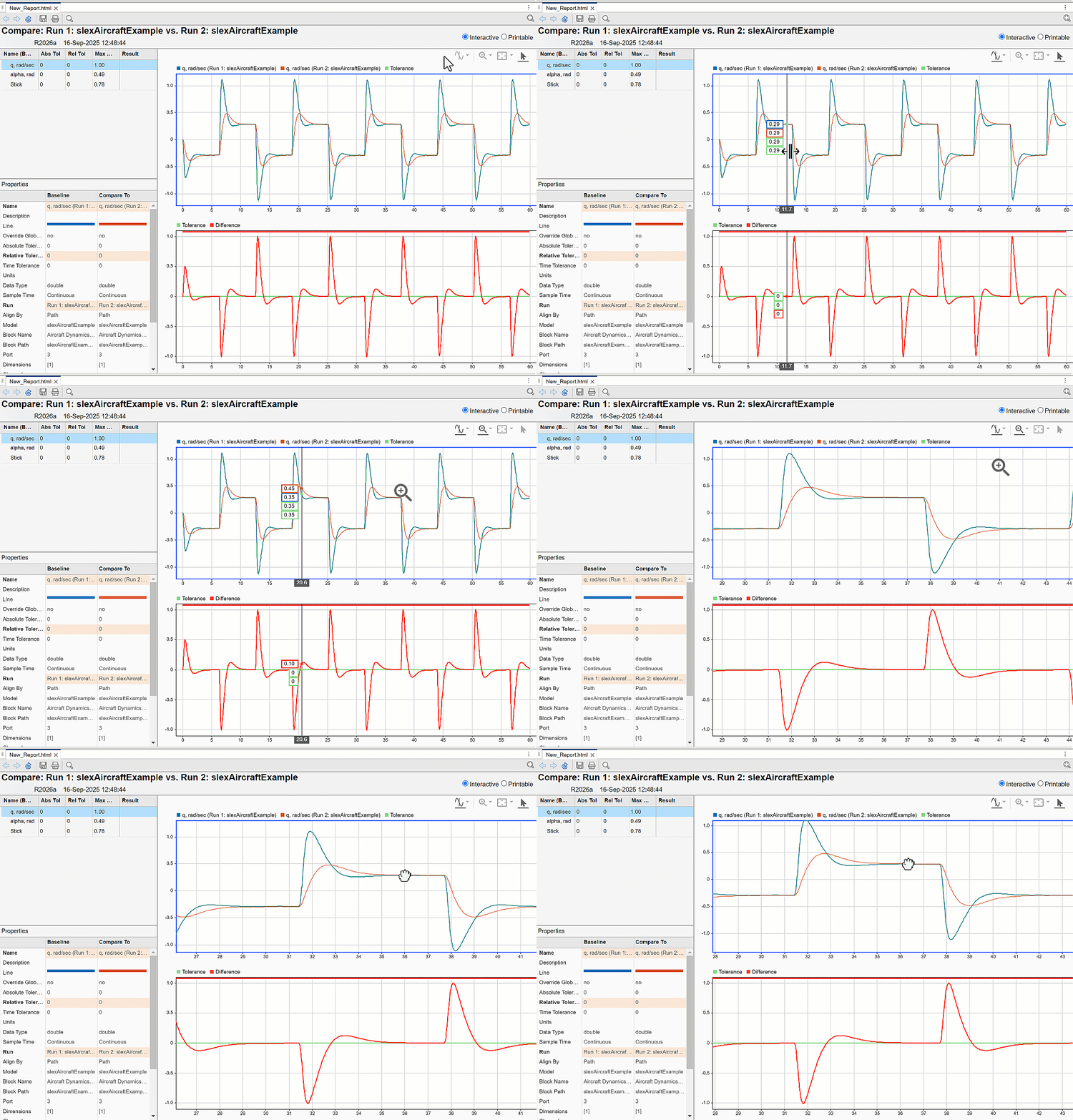
Generate comparison reports with interactive plots using Simulation Data Inspector
Comparison reports in the Simulation Data Inspector let you share comparison data without MATLAB dependency. When you generate comparison reports from the Simulation Data Inspector, the plots are now interactive. You can zoom, pan and use data cursors in the plots. Prior to R2026a, plots were static images that did not have any interactive functionality.
For more information about generating comparison reports, see Create Interactive Comparison Reports.
Accelerate JIT simulation with additional SIMD support
In R2026a, if your hardware supports the AVX2 or AVX512F SIMD instruction sets, you can use Hardware acceleration to speed up the simulation of just-in-time (JIT) models.
Run large-scale, system-level studies using parsim and Amazon Web Services
(AWS)
The new example Scaling Virtual Calibration and System Design with parsim and AWS shows how to run large-scale, system-level studies using parsim and AWS.
Functionality being removed or changed
The Simulation Data Inspector no longer exports data to the workspace by default when you create a new session or delete signals or runs
Behavior change
When you create a new session or delete runs or signals, the Simulation Data Inspector no longer exports data to the workspace before deleting signals or runs from the repository.
Componentization Techniques for Simulink Models: Self-paced, interactive course available as part of Online Training Suite subscription
Componentization Techniques for Simulink Models is a new course that teaches you to:
Manage large Simulink models by organizing them into reusable components.
Select componentization strategies to enhance collaboration.
Build scalable model architectures.
Protect your models to help safeguard your intellectual property.
For more information, see Componentization Techniques for Simulink Models.
Check for optimal model reference rebuild setting to avoid unnecessary compilations
To check that you are using the optimal model reference rebuild setting, in the Upgrade Advisor, run the Check if the model reference rebuild setting is optimal check.
Setting the Rebuild configuration parameter of the top model in
a model hierarchy to If changes in known dependencies detected
reduces the time required for change detection. The software automatically identifies most
dependencies. However, in rare cases, to prevent invalid simulation and code generation
results, you must explicitly specify dependencies on files that contain code executed by
callbacks. For more information about known and specified dependencies, see Model dependencies.
For information about running checks in the Upgrade Advisor, see Upgrade Models Using Upgrade Advisor.
Create Model Hierarchy with Subsystems: Self-paced, interactive course available as part of Online Training Suite subscription
Create Model Hierarchy with Subsystems is a new course that teaches you to:
Reduce complexity and improve readability of Simulink models by grouping related blocks into subsystems.
Create and customize parameter dialog boxes for subsystems using masks.
Control the execution of your model by creating subsystems that execute in response to a control signal.
For more information, see Create Model Hierarchy with Subsystems.
Model System Components: Self-paced, interactive course available as part of Online Training Suite subscription
Model System Components is a new course that teaches you to:
Build larger projects for complex systems with multiple components.
Create and reference components as subsystems, separate models, or reusable libraries.
For more information, see Model System Components.
Check model componentization for faster model compilation
To speed up model compilation by converting subsystems to referenced models, in the Performance Advisor, run the Check model componentization check.
This check finds identical subsystems that have the same block diagram and interface. The check determines whether the subsystems satisfy at least one threshold criteria and converts the subsystems to referenced models where beneficial. The threshold criteria are the specified minimum number of copies and minimum number of constituent blocks.
This check is not run by default because it compiles the model hierarchy multiple times, which can be time consuming.
For more information about running checks in the Performance Advisor, see Improve Simulation Performance Using Performance Advisor.
Faster loading of model containing many instances of same referenced model
Loading a model that contains many instances of the same referenced model is faster in R2026a than in R2025b. The more times you reference the same model, the larger the performance improvement you experience.
For a simple example, suppose you create a model that references the
vdp model many times. Open an example that uses the
vdp model. Check that the vdp model is
closed.
openExample("simulink_general/VanDerPolOscillatorExample") close_system("vdp")
The following function creates a model that references the vdp model
the number of times specified by num_instances. The function saves and
closes the new model hierarchy and times how long it takes to load the top model.
function t = timingTest(num_instances) % Create top model topModel = "top"; new_system(topModel); open_system(topModel); % Add num_instances of vdp to top refModel = "vdp"; for i = 1:num_instances add_block("simulink/Ports & Subsystems/Model", ... topModel+"/Model",MakeNameUnique="on", ... ModelName=refModel); end % Save and close top model close_system(topModel,1); % Measure performance of load_system function tic; load_system(topModel); t = toc; % Close and delete top model close_system(topModel); topFile = topModel+".slx"; delete(topFile); end
Loading a model that contains 10 to 100 instances of a referenced model like
vdp is about 1.9–2.8x faster than in the previous release.
This table provides the approximate execution times.
| Number of Instances | R2025b | R2026a |
|---|---|---|
| 10 | 0.34 s | 0.18 s |
| 20 | 0.43 s | 0.23 s |
| 50 | 0.80 s | 0.40 s |
| 100 | 1.6 s | 0.57 s |
This evaluation was performed on a Windows 11, AMD EPYC™ 74F3 @ 3.19 GHz test system.
For more information about model references, see Model Reference Behavior and Capabilities.
Faster saving for large model reference hierarchies
Saving a model hierarchy that contains many modified referenced models is faster in R2026a and R2025b than in R2025a. The more modified referenced models and levels of model hierarchy, the larger the performance improvements you experience.
The following function creates a vertical model reference hierarchy composed of the number
of models specified by num_models. The function modifies each model in
the hierarchy and times how long it takes to save the models. The function uses a temporary
directory. After timing, the function closes the models and removes the temporary
directory.
function t = timingTest(num_models) % Navigate into temporary directory currDir = pwd; tempDir = tempname; mkdir(tempDir) cd(tempDir) % Track created models createdModels = cell(1,num_models); topModel = "Model1"; % Create the hierarchy: Model1 -> Model2 -> ... -> ModelN for i = num_models:-1:1 mdl = sprintf("Model%d",i); createdModels{i} = mdl; new_system(mdl); open_system(mdl); if i < num_models refName = sprintf("Model%d", i+1); add_block("simulink/Ports & Subsystems/Model", ... mdl+"/Model",ModelName=refName); end save_system(mdl); end % Make all models in hierarchy dirty cellfun(@(x) set_param(x,Description="Dirty"),createdModels); % Measure performance of save_system function tic; save_system(topModel,SaveDirtyReferencedModels="on"); t = toc; % Close created models cellfun(@(x) close_system(x), createdModels); % Remove temporary directory and created models cd(currDir) rmdir(tempDir,"s") end
The performance improvement increases with the number of modified referenced models and levels of model hierarchy:
For a vertical model reference hierarchy that contains 10 modified models, saving the models is about 2x faster than in R2025a.
For a vertical model reference hierarchy that contains 50 modified models, saving the models is about 4x faster than in R2025a.
This table provides the approximate execution times.
| Number of Models | R2025a | R2025b | R2026a |
|---|---|---|---|
| 10 | 1.5 s | 0.82 s | 0.86 s |
| 20 | 3.6 s | 1.7 s | 1.6 s |
| 30 | 6.4 s | 2.9 s | 2.4 s |
| 50 | 17 s | 4.6 s | 4.2 s |
This evaluation was performed on a Windows 11, AMD EPYC 74F3 @ 3.19 GHz test system.
For more information about model references, see Model Reference Behavior and Capabilities.
Linearly interpolate outputs of model references configured to use local solvers
When a parent solver takes a step that does not correspond to a communication step for a local solver, Model blocks that reference models configured to use a local solver provide an interpolated output value to the parent solver. You can now configure Model blocks that produce real, double, continuous output signals to linearly interpolate these output values.
To configure a model reference to linearly interpolate output values, set the
Output signal handling parameter of the Model block
to Linear. For parent solver time steps that do not correspond to
communication steps, the Model block provides outputs by linearly
interpolating the output value from the last communication step and the value the local
solver computed for the next communication step.
When you set Output signal handling to
Auto, the software now selects linear interpolation in some
cases. For details, see Auto output signal handling selects linear interpolation in some cases.
Linear output signal handling has these advantages over zero-order hold output signal handling:
Simulation results are closer to the results of a simulation that uses a single solver.
Output signal sample times do not change across the model reference boundary.
Retaining continuous sample time across the model reference boundary can result in fewer parent solver resets.
In previous releases, only zero-order hold output signal handling was supported for variable-step local solvers and for fixed-step solvers that have a smaller step size than the parent solver.
For more information, see Use Local Solvers in Referenced Models.
Use local solvers for models that reference hybrid models
Local solvers are now supported for referenced models that directly or indirectly reference another model that has both continuous and discrete sample times.
In previous releases, local solvers are not supported for such model references, with a couple exceptions.
For more information, see Use Local Solvers in Referenced Models.
Reference hybrid, fixed-step model from variable-step parent
A variable-step model can now reference a fixed-step, single-tasking model that has both continuous and discrete sample times.
For more information, see Specify Compatible Solver Settings.
Assign new bus objects and identify mismatches at bus element ports more easily
When a bus element port does not specify a Simulink.Bus object, you can
now create and assign Simulink.Bus objects from the Property
Inspector or port dialog box by clicking
. The software compiles the model and then creates and
assigns the Simulink.Bus objects. In previous releases, creating and
assigning Simulink.Bus objects to bus element ports requires multiple
steps.
When you create Simulink.Bus objects after opening the
Property Inspector or port dialog box, to update the Data
type list, select Refresh data types from the
list. In previous releases, clicking
updates the entire dialog box, including the
Data type list.
When a bus element port specifies a Simulink.Bus object
and the incoming bus hierarchy does not match the specified bus object, the Property
Inspector and port dialog box now display only the mismatched elements in red.
Mismatched elements include:
Elements that are accessed by blocks but are missing from the bus object
Elements that are specified by bus objects but do not match incoming elements
Parents of mismatched elements
In previous releases, when an element does not match, the entire bus hierarchy is red, not just the mismatched elements.
For more information, see In Bus Element and Out Bus Element.
Propagate names between bus element ports and components more intuitively
When you connect an In Bus Element or Out Bus Element block to a port on a Subsystem block, a custom port or element name replaces a default port or element name. Previously, the software ignored element names when renaming.
For a custom name from a port on a Model block to replace a default port or element name at an In Bus Element or Out Bus Element block, the referenced model must be loaded. The names of the ports on a Model block are determined by the referenced model and are not changed.
For more information, see Connect Port Blocks to Subsystems.
Successively add bus elements to bus element ports
When you add an element to a bus in a bus element port, the selection remains on the parent instead of changing to the new element. You can now add multiple elements to a bus without reselecting the parent before adding each element.
For an example, see Specify Multiple Input Signals at One Port.
Initialize Model blocks by specifying initial operating points
You can now load a partial operating point for simulation by specifying the initial operating point of one or more Model blocks in the model hierarchy. When you specify an initial state or operating point for the top model, you can specify a Model block operating point to override the state or operating point information for the block.
In previous releases, you had to specify a complete operating point for the top model. The operating point of the top model initializes the entire model hierarchy.
You can configure multiple Model blocks in the same model hierarchy to save
the final operating point or simulate from an initial operating point. By default, each
Model block operating point is saved as a Simulink.op.ModelBlockOperatingPoint object in a property of the Simulink.SimulationOutput object returned by the simulation.
Saving and loading Model block operating points is not supported for Model blocks that:
Simulate in a mode other than normal mode
Reference a model that is referenced by another Model block in the hierarchy
Are part of a variant subsystem or variant assembly subsystem
Count all blocks used in system and its references using sldiagnostics
Using sldiagnostics, you can now count all blocks used in a system and its references by setting the CountBlocksInRefs option.
Merge Simulink cache file contents
When you generate multiple Simulink cache files for the same model, you can now merge the contents of those files in one Simulink cache file. To support the merge, platform-specific artifacts, such as simulation and code generation targets, must be unique. For example, the cached model reference simulation targets must have different releases or platforms than each other.
To merge Simulink cache file contents in a new file, use the slxcmerge
function. For more information, see slxcmerge.
Easily copy subsystem content to new model after failed conversion
When the Model Reference Conversion Advisor fails to convert a subsystem to a model, the advisor now provides an option to copy the subsystem block diagram to a new model. The new model uses the configuration set from the original parent model. If you want to force the conversion and resolve errors manually after the conversion, use this option.
For more information about the conversion process, see Convert Subsystems to Referenced Models.
Models created from subsystems can retain Polyspace comments
When you convert a subsystem to a model, you can now retain Polyspace comments specified by the PolySpaceStartComment and
PolySpaceEndComment block property tokens. To copy the Polyspace comments from the subsystem to the new model, use the Simulink.SubSystem.convertToModelReference function with
CopyPolyspaceComments set to true.
For information about block property tokens, see Specify Block Properties.
Simulink Units: Ordinal units specifications now supported
Simulink now supports ordinal unit specifications, such as
beaufort_wind_scale. Blocks now support units that provide relative
ranking, but the intervals between the values are not evenly distributed.
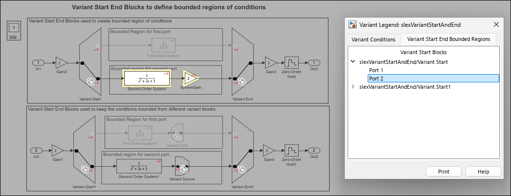
Highlight bounded regions of Variant Start and Variant End blocks for enhanced visual representation
You can now highlight the blocks within a bounded region created by Variant Start and Variant End blocks to distinguish them visually from other components. This feature enables you to trace data flow and logic specific to each variant implementation in large and complex models.
Consider the slexVariantStartAndEnd model, which contains the
Variant Start and Variant End blocks that define the
bounded regions.
To identify the blocks within the bounded region created at Port 2 of the Variant Start block:
In the Simulink Toolstrip, on the Debug tab, select Information Overlays > Start End Bounded Regions.
On the Variant Start End Bounded Regions tab, expand slexVariantStartAndEnd/Variant Start and choose Port 2. Alternatively, click the output signal connected to Port 2 of the Variant Start block to highlight the blocks within its bounded region.
Block highlighting applies only to the model in which it is enabled and does not extend to the bounded regions in the referenced models. To highlight blocks within a bounded region of a referenced model, open the referenced model and select the Start End Bounded Regions option within that model. For more information, see Control Variant Condition Propagation using Variant Start and Variant End Blocks.
Variant Manager for Simulink: Use instance-specific values for variant control variables
Starting in R2026a, Variant Manager supports instance-specific values for variant control variables when you define these variables in the model workspace and configure them as model arguments.
When you configure a variant control variable as a model argument and reference the model using multiple Model blocks, you can assign either the same value or different values to each instance of the variable in the model hierarchy. The instance-specific value for this variable can come from the model workspace of the referenced model, the parent model reference hierarchy, or a system mask applied to the referenced model. Variant Manager identifies this instance-specific definition and uses it when importing control variables, finding control variable usage, and activating the model.
For more information on the use of instance-specific values, see Configure Instance-Specific Values for Block Parameters in a Referenced Model.
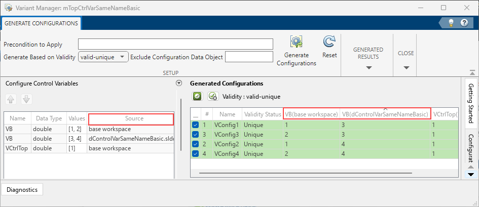
Variant Manager for Simulink: Use variant control variables with the same name defined in multiple sources when generating configurations
When you automatically generate variant configurations by using Variant Manager or the
Simulink.VariantManager.generateConfigurations function, you can use
variant control variables with the same name defined in multiple sources, except in the
preconditions to be applied when generating configurations.
In the Generate Configurations tab of the Variant Manager window, the Configure Control Variables table has a new Source column that shows the source of the control variables used by the model hierarchy. The generated configurations also identify variables with multiple definitions by their source.
Variant Manager for Simulink: Open Variant Manager using Simulink.VariantManager.open
function
You can now use the Simulink.VariantManager.open function to open Variant Manager from the
MATLAB command line. You can provide a block diagram name, a block path, or a Simulink.BlockPath object as input to this function. You can also use this
function to open the Simulink.VariantConfigurationData object dialog
box to define and edit variant configurations and constraints without a Simulink model.
Variant Manager for Simulink: Analyze variant models using
Simulink.VariantManager.analyzeModel function
You can use the Simulink.VariantManager.analyzeModel function to programmatically analyze
variant configurations for a model. Specify either named variant configurations or variable
groups as input to the function.
The function analyzes the model using the specified configurations and opens the variant
analysis report. This is the default behavior if you do not specify an output argument in the
function call. The function can also return a Simulink.VariantConfigurationAnalysis object as an output argument. You can call
functions of this object to perform further operations on the analysis results.
For more information on Variant Analyzer, see Analyze Variant Configurations in Models Containing Variant Blocks.
Variant Manager for Simulink: Simulation support for models with variant configuration data without installing support package
Starting in R2026a, you can simulate models that have variant configurations defined and
stored in an associated Simulink.VariantConfigurationData object without
installing the Variant Manager for Simulink support package.
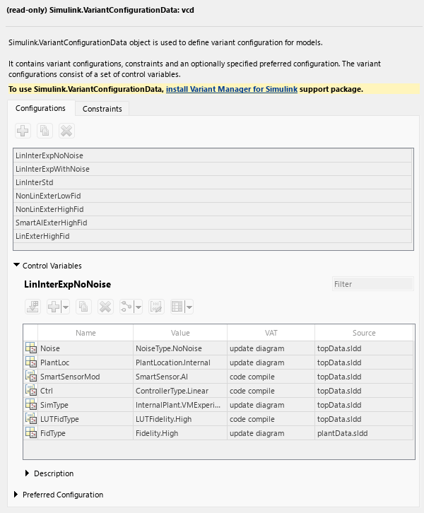
You can view the variant configurations and constraints saved in the
Simulink.VariantConfigurationData object. If the object is defined in the
base workspace, double-click the object or use the open function at the
MATLAB command line. If the object is in a data dictionary, select the object in the
Model Explorer. Selecting the object opens the
Simulink.VariantConfigurationData dialog box in a read-only mode. For more
information, see Manage Variant Configurations Without Simulink Model.
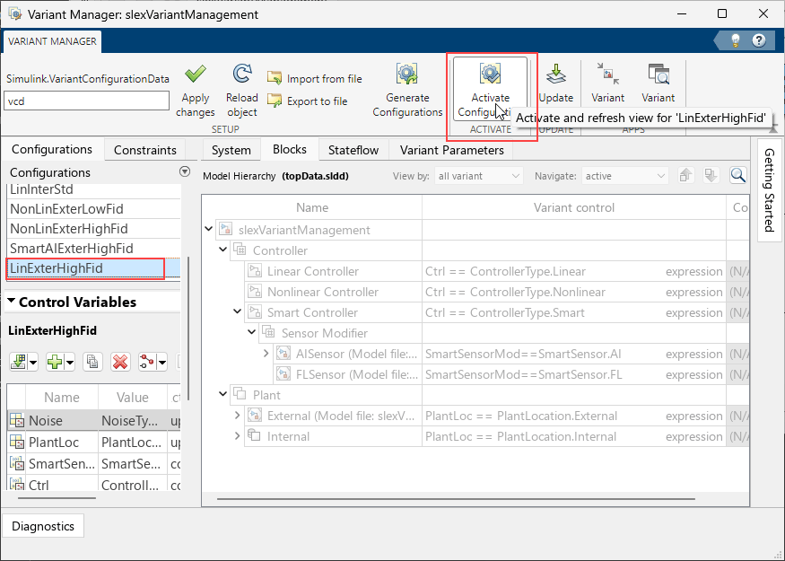
You can run single or multiple parallel simulations on the model programmatically without specifying a named variant configuration. For example, these commands run successfully without the support package installed:
openExample("slexVariantManagement.slx"); sim("slexVariantManagement.slx")
Simulink.SimulationInput object by specifying a named variant
configuration, as shown below, results in an error if the support package is not
installed.simInp = Simulink.SimulationInput("slexVariantManagement.slx") simInp = setVariantConfiguration(simInp,'LinInterExpWithNoise') sim(simInp,"ShowProgress","on");
Previously, since R2022b, you could not simulate models containing variant configurations unless you installed the Variant Manager for Simulink support package.
Variant Manager for Simulink: Reduce models containing Function Element and Function Element Call blocks
Variant Reducer now supports reducing models that contain Function Element and Function Element Call blocks.
Variant Manager for Simulink: Specify arguments of Simulink.VariantConfigurationData object
functions using Name=Value syntax
Starting in R2026a, functions of the Simulink.VariantConfigurationData object support specifying input arguments using
the Name=Value syntax. This enhancement improves usability and aligns the
syntax with other functions provided by Variant Manager for Simulink. Functions of the Simulink.VariantConfigurationData object
continue to support positional arguments, but it is recommended to use the
Name=Value syntax instead.
For example, the following table compares the positional argument syntax and the newly
supported Name=Value syntax for the addConfiguration function. Here, varconfigdata is a
Simulink.VariantConfigurationData object.
| Before R2026a | From R2026a |
|---|---|
addConfiguration(varConfigData, ... "InternalPlantConfig", ... "Internal Plant Controller", ... ctrlVarStruct); |
addConfiguration(varConfigData, ... ConfigurationName="InternalPlantConfig", ... Description="Internal Plant Controller", ... ControlVariables=ctrlVarStruct); |
Variant Manager for Simulink: Improved performance when activating named variant configurations
In R2026a, when you activate a named variant configuration in Variant Manager for Simulink, the operation completes sooner for large models that contain many referenced models compared to R2025b.
Optimize block activation by propagating variant conditions through signal loops
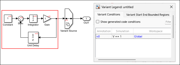
In previous releases, variant conditions specified in variant blocks did not propagate to the blocks that form signal loops. The blocks forming these loops remained active during simulation and code generation. Starting in R2026a, variant conditions propagate through signal loops. The blocks inside and outside the loop along the signal path activate or deactivate based on their associated variant conditions. As a result, only blocks required for the active variant are simulated and included in the generated code, eliminating the unnecessary inclusion of inactive blocks.
For example, in this model, the variant condition V == 1 from the
Variant Source block propagates to the Sum,
Integrator, Gain, and Unit Delay blocks
that form the signal loop and to the Constant block outside the loop. These
blocks activate only when V == 1 evaluates to
true.
Convert referenced subsystem to a regular subsystem from the Simulink Editor
You can now convert a Subsystem Reference block to a Subsystem block directly from the Simulink Editor by using either of these ways:
Right-click the Subsystem Reference block and select Convert to > Subsystem.
Select the Subsystem Reference block, go to the Subsystem Block tab, and select Convert > Convert to Subsystem.
Previously, you could convert a Subsystem Reference block to a Subsystem block only from the MATLAB Command Window.
For more information, see Convert Subsystem Reference Block to Subsystem Block in Convert Between Subsystems and Referenced Subsystems.
Change active variant during run time using Simulation object
Starting in R2026a, you can switch the active variant during simulation by using the
setVariable or setBlockParameter function of a
Simulation object to write to a variant control variable while
simulation is paused. Previously, you could switch the active variant choice of a
Variant Subsystem block during simulation or execution of the generated
code only by using a Parameter Writer block to write to a variant control
variable.
This code pauses a simulation, then demonstrates how to switch the active variant choice for different locations of the variant control variable.
% start simulation mdl = "runtimeVariant"; open_system(mdl); s = simulation(mdl) % update variant control variable stored in a global workspace s = setVariable(s,"V",0); step(s,PauseTime=5); s = setVariable(s,"V",1); % update variant control variable that is a Simulink.Parameter object stored in a model workspace s = setVariable(s,"M.Value",int32(1),"Workspace","runtimeVariant"); step(s,PauseTime=5); s = setVariable(s,"M.Value",int32(2), "Workspace","runtimeVariant"); % update variant control variable stored in a mask workspace s = setBlockParameter(s,"runtimeVariant/MaskSubsystem","V","1"); step(s,PauseTime=5); s = setBlockParameter(s,"runtimeVariant/MaskSubsystem","V","2"); % update a variant control variable as a model argument s = setBlockParameter(s,"runtimeVariant/Model", "ParameterArgumentValues", struct("V","1")); step(s,PauseTime=5); s = setBlockParameter(s,"runtimeVariant/Model", "ParameterArgumentValues", struct("V","2")); % resume simulation step(s,PauseTime=10); out = stop(s);
For more information, see Control Active Choice of Variant Subsystem During Simulation or Execution of Generated Code.
Visualize connection between Parameter Writer block and base workspace or model workspace variables
Starting in R2026a, you can visualize the connection from a Parameter Writer block to a base workspace or model workspace variable in the Connectors tool. For example, you can now visualize the connection between a Parameter Writer block writing to a variant control variable in the base workspace and a Variant Subsystem block as the parameter owner block. Previously, when you selected Parameter Connectors, the Connectors tool displayed the connection from a Parameter Writer block only when the destination was a block parameter.
To display the connection to workspace variables, in the Connectors tool, select Parameter Connectors. Then, compile the model.
The Connectors tool is available in the Information Overlays menu on the Debug tab of the Simulink Editor.
For more information on using the Connectors tool, see Use Connectors Tool to Visualize Relation Between Blocks.
Generate code for Parameter Writer block with inlined parameters
Starting in R2026a, you can generate code for a Parameter Writer block, writing
to a variable with non-auto storage class attributes, with inlined parameters by setting the
model parameter to Inlined. Previously, you could only generate
code for a Parameter
Writer block when the model configuration parameter Default
parameter behavior (Simulink Coder) was set to Tunable.
For example, you can now generate code for a Parameter Writer block that writes to the run-time variant control variable for a Variant Subsystem block regardless of the Default parameter behavior setting.
Use Parameter Writer block to initialize variant control value of variant parameter bank
In R2025a, you could use Parameter Writer blocks within an Initialize
Function block to initialize Simulink.VariantControl objects
associated with variant parameters (Simulink.VariantVariable) that have a startup
activation time. Starting in R2026a, you can use variant parameter banks (Simulink.VariantBank) to group such variant parameters.
With this enhancement, the Parameter Writer block can initialize the variant
control used by the variant parameter bank, enabling you to select the active choice of the
bank at the start of simulation or during the initialization of generated code. You must
define both the variant parameters and the variant parameter bank in the base workspace or in
a data dictionary associated with the model. In the code generated by Embedded Coder®, the Parameter Writer block initializes the
Simulink.VariantControl object, which in turn selects the active value set
from the variant parameter bank structure array. For an example, see Initialize Variant Control Value of Variant Parameter Bank Using Parameter
Writer Block.
For information on code generation using variant parameter banks, see Group Variant Parameter Values and Conditionally Switch Active Value Sets in Generated Code (Embedded Coder).
Generate code for model that references protected model containing variant parameters with
code compile activation time
In R2026a, you can generate code for a model that includes a protected model when the
protected model contains variant parameters with code compile
variant activation time. The generated code for the parent model does not contain preprocessor
conditional statements for the declarations and definitions of these variant parameters. This
code is similar to code generated for such a model when you set the variant parameter
activation time to update diagram analyze all choices.
In this example, the parent model refers to a protected model that uses two variant
parameters K and Kv, that use a variant control
V, with code compile activation time.
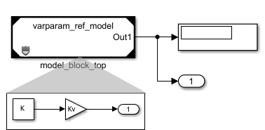
When you generate code for this model using Embedded Coder, the code for the parent model defines the variant parameters without
conditionally compiling them based on variant control V, and the code
contains only the active choice of the variant
parameters.
/* File: varparam_top_model.h */
/* Model block global parameters (default storage) */
extern real_T rtP_K; /* Variable: K
* Referenced by: '<Root>/model_block_top'
*/
extern real_T rtP_Kv; /* Variable: Kv
* Referenced by: '<Root>/model_block_top'
*//* File: varparam_top_model_data.c */
/* Model block global parameters (default storage) */
real_T rtP_K = 2.0; /* Variable: K
* Referenced by: '<Root>/model_block_top'
*/
real_T rtP_Kv = 3.0; /* Variable: Kv
* Referenced by: '<Root>/model_block_top'
*/
/* File: varparam_ref_model.c */
/* Output and update for referenced model: 'varparam_ref_model' */
void varparam_ref_model(real_T *rty_Out1)
{
/* Gain: '<Root>/Gain' incorporates:
* Constant: '<Root>/Constant'
*/
*rty_Out1 = rtCP_Gain_Kv * rtCP_Constant_K;
}If the parent model uses the same variant parameter as the protected model with
code compile activation time, then the generated code for the
parent model guards that variant parameter using the preprocessor conditionals
#if and #elif.
In this example, the parent model also uses the variant parameter
K.
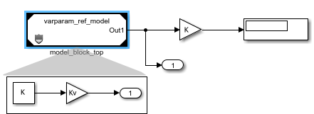
The code generator uses the macro V to emit #if and
#elif guards that conditionally compile
K.
/* File: varparam_top_model_has_vparam_types.h */
#ifndef V
#define V 1
#endif/* File: varparam_top_model_has_vparam.h */
/* Model block global parameters (default storage) */
#if V == 1 || V == 2
extern real_T rtP_K; /* Variable: K
* Referenced by: '<Root>/model_block_top'
*/
#endif
extern real_T rtP_Kv; /* Variable: Kv
* Referenced by: '<Root>/model_block_top'
*//* File: varparam_top_model_has_vparam_data.c */
/* Model block global parameters (default storage) */
real_T rtP_Kv = 3.0; /* Variable: Kv
* Referenced by: '<Root>/model_block_top'
*/
#if V == 1
real_T rtP_K = 2.0; /* Variable: K
* Referenced by: '<Root>/model_block_top'
*/
#elif V == 2
real_T rtP_K = 4.0; /* Variable: K
* Referenced by: '<Root>/model_block_top'
*/
#endifImproved error handling for models with variants and buses
Simulink no longer reports bus propagation errors for inactive variant paths or blocks with Variant activation time set to update diagram.
For more information on using Variant Subsystem blocks, see Implement Variations in Separate Hierarchy Using Variant Subsystems.
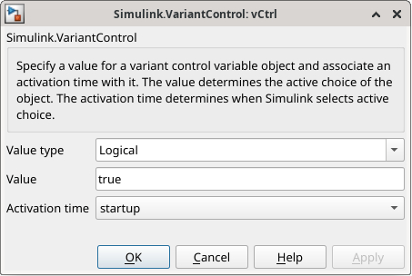
Specify value of Simulink.VariantControl as Boolean value
Starting in R2026a, you can specify the value of Simulink.VariantControl objects as Boolean values. You can also set the value of
a variant control object to a Simulink.Parameter object with a Boolean value.
This enhancement is supported for simulation and code generation workflows, including code
generation targets such as AUTOSAR. For
example,
vCtrl = Simulink.VariantControl(Value=true,ActivationTime="startup");vCtrlSP = Simulink.VariantControl(Value=Simulink.Parameter(Value=true));
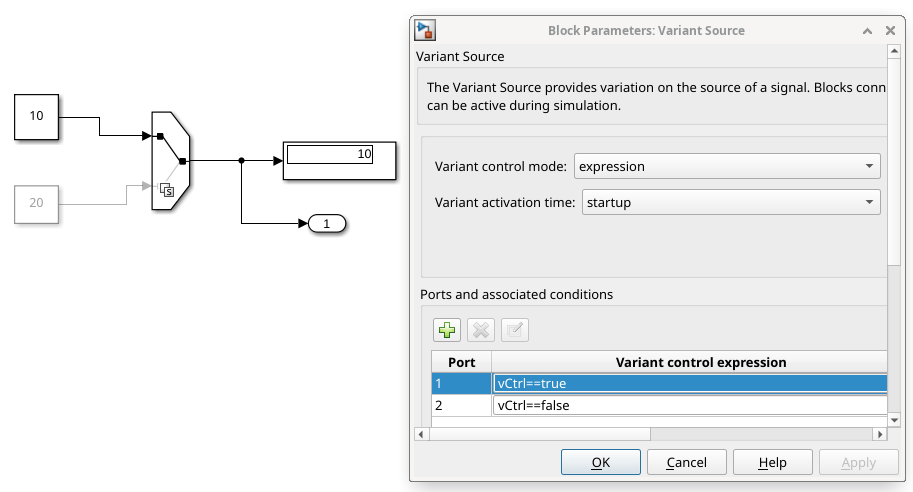
This model uses a Simulink.VariantControl object vCtrl
with a Boolean value to switch between the choices of a Variant Source
block.
This code snippet shows the definition of the variant control vCtrl and
its usage in the model step function in the code generated using Simulink
Coder™.
/* Exported block parameters */
boolean_T vCtrl = true; /* Variable: vCtrl
* Referenced by:
* '<Root>/Constant'
* '<Root>/Constant1'
* '<Root>/vCtrl'
*/
/* Model step function */
void modelVCwithBool_step(void)
{
/* SignalConversion generated from: '<Root>/Variant Source' */
if (vCtrl) {
/* Outport: '<Root>/Out1' incorporates:
* Constant: '<Root>/Constant'
*/
modelVCwithBool_Y.Out1 = modelVCwithBool_P.Constant_Value;
} else {
/* Outport: '<Root>/Out1' incorporates:
* Constant: '<Root>/Constant1'
*/
modelVCwithBool_Y.Out1 = modelVCwithBool_P.Constant1_Value;
}
}Group member definitions of integer-based enumerated types using
Members argument
When defining integer-based enumerated types using the Simulink.defineIntEnumType function, you can use the new argument
Members to group each member’s name, value, and description into a
single cell array. The member description is a new and optional property.
Consider the enumeration named Colors with three members,
Red, Yellow, and Green. Each
member has an associated integer value and description.
| Name | Value | Description |
|---|---|---|
Red | 0 | Stop! |
Yellow | 1 | Prepare to stop! |
Green | 2 | Go! |
Use the Members argument to define the name, value, and description for
each member of the enumerated type Colors in a single array.
Simulink.defineIntEnumType("Colors", ...
"Members",{{"Red",0,"Description","Stop!"}, ...
{"Yellow",1,"Description","Prepare to stop!"}, ...
{"Green",2,"Description","Go!"}}, ...
"Description"="Traffic light colors", ...
"DefaultValue"="Red", ...
"StorageType"="int16");
The generated code includes the description for each member as a comment next to the corresponding enumeration member.
typedef enum {
Red= 0, /* Stop! (default value) */
Yellow /* Prepare to stop! */
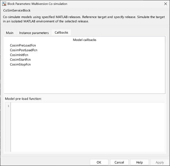
Green /* Go! */} Colors;Specify Callback Functions for Multiversion Co-Simulation Components in Block Dialog
You can now specify callback functions for Multiversion Co-simulation components in the Multiversion Co-simulation block dialog. These are the supported block callbacks and their corresponding model callbacks in Simulink.
CosimPreLoadFcn - PreLoadFcn
CosimPostLoadFcn - PostLoadFcn
CosimInitFcn - InitFcn
CosimStartFcn - StartFcn
CosimStopFcn - StopFcn
Before R2026a, only PreLoadFcn and PostLoadFcn were supported and had to be defined in a separate script. You can now manage component callbacks directly on the block dialog.
Simulink.importExternalCTypes: Enhanced Support For Custom Type
Import and Compiler Flags
Starting in R2026a, the Simulink.importExternalCTypes function allows
you to:
Generate a header file containing the type alias corresponding to the type
signatures from an external header file using the SimulinkTypeAliasHeader argument.
Import types with type names that contain the original type signatures from an
external header file using the UseFullyQualifiedName argument.
Add additional flags to the compiler command line using the CompilerFlags argument.
Access compiled port attributes without model recompilation
Starting in R2026a, you can access compiled port attributes — such as complexity, data type, units and width of data and state ports — in a previously compiled model without requiring the model to be in an active compilation state. This change saves time in cases where model compilation is time-consuming.
For a model that has been successfully compiled once before in the current MATLAB session, this enhancement makes accessing complexity, data type, units and
width attributes simpler. The feval based compiled attribute access
continues to work as before.
For example, this table compares the access pattern for complexity in a previously compiled model for versions R2025b and earlier with the versions R2026a and later.
| R2025b and earlier | R2026a and later |
|---|---|
feval(gcs,[],[],[],"compile"); cs = get_param(gcb,"CompiledPortComplexSignals") feval(gcs,[],[],[],"term"); |
cs = get_param(gcb,"CompiledPortComplexSignals") |
Use Simulink Units with FMU block
Starting in 2026a, the input and output ports of the FMU Import block can read and propagate units. You can use signals with built-in and user-defined units at the block interface.
Simulink Support Package for Rust Code (April 2026)
Starting in R2026a, you can use the Simulink Support Package for Rust® Code to interface Rust code with Simulink. To use this support package, you must install this support package as an add-on. For more information, see Install Simulink Support Package for Rust Code.
Using the support package, you can:
Generate Rust bindings (wrappers) for C code generated from Simulink models using the Rust wrapper API, coder.RustWrapper.genRustBindings (Embedded Coder). The generated bindings provide
Foreign Function Interface (FFI) access to model functions and data. These bindings
allow Rust programs to call Simulink functions and access model data directly. To use the Rust wrapper API, you must have an Embedded Coder license. For more information, see Generate Rust Bindings for Simulink Generated C Code (Embedded Coder).
Integrate C compatible Rust code into Simulink using the Rust Importer wizard. This allows you to simulate and test custom Rust code using Simulink model components. For more information, see Import C Compatible Rust Code into Simulink Using the Rust Importer Wizard.
Functionality being removed or changed
Rebuild configuration parameter default value is now
If changes in known dependencies detected
Behavior change
By default, new models set Rebuild to If changes
in known dependencies detected instead of If changes
detected. The new default value reduces the time required for change
detection.
The software automatically identifies most dependencies. However, in rare cases, to prevent invalid simulation and code generation results, you must explicitly specify dependencies on files that contain code executed by callbacks. For more information about known and specified dependencies, see Model dependencies.
Rebuild and Never rebuild diagnostic configuration parameters will be removed
Warns
The Rebuild and Never rebuild diagnostic configuration parameters will be removed in a future release.
In the Configuration Parameters dialog box, these parameters have been moved under Advanced parameters at the bottom of the Model Referencing pane.
The software now issues warnings when:
You update, simulate, or build a model with Rebuild
set to a value other than If changes in known dependencies
detected.
In the MATLAB Command Window, you specify an
UpdateModelReferenceTargets value other than
"IfOutOfDate".
In the MATLAB Command Window, you specify a
CheckModelReferenceTargetMessage value.
The future behavior will match the If changes in known dependencies
detected setting of the Rebuild configuration
parameter.
To rebuild model reference targets conditionally, set
Rebuild to If changes in known
dependencies detected. To check for changes in files that contain
code executed by callbacks, use the Model dependencies
configuration parameter. For more information, see Model dependencies.
To rebuild model reference targets unconditionally, remove the related Simulink cache files and model reference targets. For more information, see Manage Simulation Targets for Referenced Models and Manage Build Process Folders (Simulink Coder).
To avoid rebuilding model reference targets, convert the referenced models to protected models. For more information, see Protect Models to Conceal Contents (Simulink Coder).
UpdateThisModelReferenceTarget argument of
slbuild function will be removed
Warns
The UpdateThisModelReferenceTarget name-value argument of the
slbuild function will be
removed in a future release. This argument lets you build the model reference
simulation or coder target for only the specified model and not its referenced
models.
To avoid rebuilding model reference targets for referenced models, convert the referenced models to protected models instead. For more information, see Protect Models to Conceal Contents (Simulink Coder).
To control what model reference targets build during simulation or code generation, use the strategies in this table instead.
UpdateThisModelReferenceTarget
Value | Recommended Replacement |
|---|---|
"IfOutOfDate" or
"IfOutOfDateOrStructuralChange" | To rebuild model reference targets
conditionally, set the
|
"Force" | To rebuild model reference targets unconditionally, remove the related Simulink cache files and model reference targets. For more information, see Manage Simulation Targets for Referenced Models and Manage Build Process Folders (Simulink Coder). |
Enable parallel model reference builds configuration parameter no longer has dependencies
Behavior change
The Enable parallel model reference builds configuration
parameter no longer depends on the Rebuild and Never
rebuild diagnostic configuration parameters. When
Rebuild is set to Never, the
software does not rebuild model reference targets, and the Enable parallel
model reference builds configuration parameter does not start a parallel
pool of workers.
Previously, the Enable parallel model reference builds
configuration parameter was disabled when Rebuild was set to
Never and Never rebuild diagnostic
was set to None.
For more information, see Enable parallel model reference builds.
Port and parameter mismatch and Model block version mismatch configuration parameters will be removed
Still runs
The Port and parameter mismatch and Model block version mismatch diagnostic configuration parameters will be removed in a future release. After removal, Model blocks will refresh without diagnostics for port, parameter, or version mismatches. This behavior is the current default behavior.
To update your code, remove commands that interact with the
ModelReferenceIOMismatchMessage and
ModelReferenceVersionMismatchMessage configuration
parameters.
For more information about Model block refreshes, see Refresh Model Blocks.
Models created from subsystems use referenced configuration sets with overridden parameter values
Behavior change
When you convert a subsystem to a model, and the parent model references a freestanding configuration set, the new model is more likely to reference the configuration set. Suppose the configuration set has parameter values that prevent the new model from being used as a referenced model. To support using the new model as a referenced model, the new model overrides the incompatible parameter values. The Model Reference Conversion Advisor lists the overridden parameters.
In previous releases, to support using the new model as a referenced model, the conversion copies a modified version of the configuration set to the new model.
For information about configuration references, see Share a Configuration with Multiple Models.
For information about the conversion process, see Convert Subsystems to Referenced Models.
Models created from subsystems retain initial conditions of bus element ports
Behavior change
When you convert a subsystem to a model, and the subsystem includes Out Bus Element blocks that specify initial conditions, the new model now retains these initial condition values.
In previous releases, the Initial output and Output when disabled block parameters are reset during the conversion process.
For information about initial conditions at bus element ports, see Specify Initial Conditions for Bus Elements.
For information about the conversion process, see Convert Subsystems to Referenced Models.
Model reference conversion detects unsupported device driver blocks
Behavior change
When you convert a subsystem to a model, the conversion now checks for device driver blocks, which are not supported in referenced models. When a subsystem contains a device driver block, the conversion now detects the issue and fails.
In previous releases, the conversion succeeds, but compiling or simulating the new model hierarchy results in an error.
For information about device driver blocks, see Structure of Device Driver System Object.
For information about the conversion process, see Convert Subsystems to Referenced Models.
Auto output signal handling selects linear interpolation in some
cases
Behavior change
When you set the Output signal handling parameter of a
Model block to Auto, the software selects the
output signal handling based on the configuration of the local solver and the
characteristics of the Model block outputs. The software now selects the new
linear output signal handling option in some cases. With linear output signal
handling:
Simulation results are closer to the results of a simulation that uses a single solver.
Model block output signals retain continuous sample time across the model reference boundary.
The table summarizes the output signal handling selection for Model blocks
that set Output signal handling to Auto
before R2026a and in R2026a.
| Model Block Outputs | Local Solver Configuration | Auto Selection Before R2026a | Auto Selection in R2026a |
|---|---|---|---|
| Any continuous double outputs | Variable-step | Zero-order hold | Linear |
| Fixed-step with smaller step size than parent solver | |||
All outputs have one or both of these characteristics:
| Variable-step | Zero-order
hold | |
| Fixed-step with smaller step size than parent solver | |||
| Any output supported by local solvers | Fixed-step with larger step size than parent solver | Use solver
interpolant | |
find_system arguments and Simulink.FindOptions properties have been renamed
Behavior change
Several find_system
arguments and Simulink.FindOptions properties have been renamed:
LookUnderModelBlocks has been renamed to
SearchInsideModelReferences.
LookInsideSubsystemReference has been renamed to
SearchInsideSubsystemReferences.
LookUnderMasks has been renamed to
SearchUnderMasks.
FollowLinks has been renamed to
SearchInsideLibraryLinks.
The previous names continue to work.
Variant Manager for Simulink: Consistent removal of test harnesses during model reduction
Behavior change
Starting in R2026a, when you reduce a model that has an associated internal or external
test harness, Variant Reducer removes the harness and its association from the reduced model.
The Variant Reducer summary report and the variant_reducer.log file provide
information about the removed harnesses. Additionally, you can no longer use Variant Reducer
or the Simulink.VariantManager.reduceModel function to reduce a test harness model. In
previous releases, Variant Reducer handled models with external and internal test harnesses
differently. The user interface and programmatic function did not clearly report how they
processed test harnesses.
For more information on Variant Reducer, see Reduce Variant Models Using Variant Reducer.
Variant Manager for Simulink: Change in default reduction mode for models without variant configurations
Behavior change
For models without predefined variant configurations, Variant Reducer now sets
Reduction mode to Current variant control
values by default. This mode allows you to reduce the model based on the
variant control variable values defined in the base workspace or data dictionary used by the
model. Previously, the default reduction mode for such models was Specify variant
control values.
For more information on Variant Reducer, see Reduce Variant Models Using Variant Reducer.
Enable simulation-time tuning of variant parameters in a protected model by specifying associated variant controls as tunable parameters
Behavior change
When you protect a Simulink model that uses variant parameters (Simulink.VariantVariable objects) with startup variant
activation time, make the variant parameters tunable during simulation by specifying only the
associated variant controls (Simulink.VariantControl objects) as tunable parameters. In previous releases, you
also had to specify the variant parameters as tunable.
Variant parameters with a variant activation time other than
startup are not tunable in protected models, so you cannot
select their variant controls as tunable parameters.
For example, this image shows the two variant parameters K and
Kv that use the Simulink.VariantControl object
V.
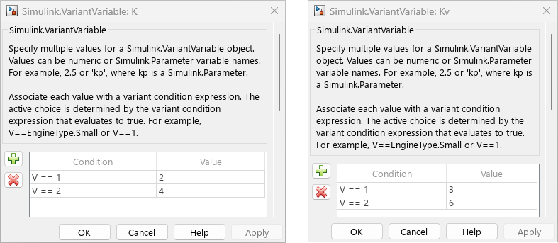
When you protect the model that uses these variant parameters by using Protected
Model Creator (Simulink Coder), select V as a tunable parameter for simulation to
configure K and Kv as tunable.
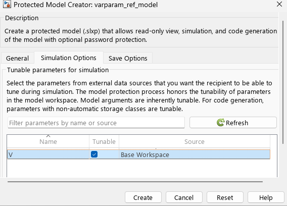
When you protect the model using the Simulink.ModelReference.protect (Simulink Coder) function, specify the
Simulink.VariantControl objects by using the TunableParameters (Simulink Coder)
name-value
argument.
Simulink.ModelReference.protect(modelName,TunableParameters=["V"]);When you get the list of tunable parameters for such a protected model using the Simulink.ProtectedModel.getTunableParameters (Simulink Coder) function, the function returns
only the Simulink.VariantControl objects that you specified as tunable
parameters.
The Simulink.ModelReference.protect function reports a warning if the
specified variant control has a variant activation time other than
startup.
Comparison Tool: Save comparison reports as PDF/A file
Starting in R2026a, you can save comparison reports as a PDF/A file interactively and
programmatically. PDF/A comparison reports are not supported on Linux®. For more information, see Export, Print, and Save Model Comparison Results and visdiff (MATLAB).
Determine if file contains System Composer block diagram, Simulink test harness, or Subsystem block without loading file
The Simulink.MDLInfo has new properties
to determine which type of model file a file without loading the file.
Use the SimulinkSubdomain property to find if the file
contains a Simulink model or a System Composer™ block diagram without loading the file.
Use the IsTestHarness property to determine if the
model file contains a Simulink test harness.
Use the IsSubsystem property to determine if the model
file contains a Subsystem block.
Compare template to blank model template
You can now compare your model templates to the blank model template directly from the Simulink Start Page. For more information, see Compare Template to Blank Model Template.
Simulink Editor prompts when model is created using non-default built-in blank template
When you create a new model from the Simulink Stat Page using a built-in blank template that is different than the default Blank Model template, the Simulink Editor now informs you about the differences and provides a hyperlink to inspect differences. Clicking on the hyperlink launches an SLTX comparison to view the configuration settings differences between the templates.
Improved comparison and merge for Simulink data dictionaries
Starting in R2026a, Simulink provides improved side by side comparison and merging of data dictionaries using the Comparison Tool and adds support for resolving conflicts in data dictionaries using the Three-Way Merge Tool.
By using these tools, you can:
Clearly highlight changes, conflicts, and merge choices for Design Data and Architectural Data sections of data dictionaries.
More easily visualize differences between dictionaries and merge choices in the context of other, unchanged elements.
Using the Three-Way Merge Tool, manually select which version of each change you want in the target file.
To programmatically publish comparison reports for data dictionaries and to automate
report generation for continuous integration (CI) workflows, use the visdiff function:
comparison = visdiff(slddFile1,slddFile2); file = publish(comparison); web(file)
For more information on data dictionary file comparison, see View and Revert Changes to Dictionary Data.
Signal Editor: Block and tool synchronization
The Open Signal Editor button in the Signal Editor block
now opens a version of the Signal Editor
tool that is synchronized with the Signal Editor block. In releases prior to
R2026a, all instances of the Signal Editor tool had the same characteristics.
For more information, see Differences Between the Signal Editors.
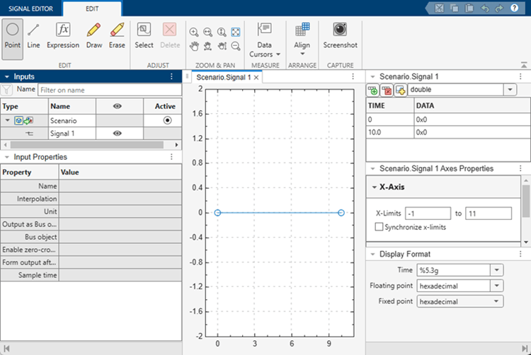
The block version of the Signal Editor tool has these changes:
When you click Open Signal Editor, the Signal Editor tool now opens populated with the active scenario. The active plot shows the last signal in the scenario.
A new Active column in the hierarchy shows the active scenario for the block. To change the active scenario, click the associated button.
New input properties support the corresponding block parameters.
| Signal Editor Block | Signal Editor Interface |
|---|---|
Output as bus object | Output a bus signal |
Bus object | Select bus object |
Enable zero-crossing detection | Enable zero-crossing detection |
Form output after final data value by | Form output after final data value by |
Sample time | Sample time |
Note
The Interpolate data and Unit
parameters of the Signal Editor tool are only reflected in the
Signal Editor block when the block parameter Use
properties from is set to Signal data in MAT
file.
To change the active scenario in the Signal Editor tool, click the associated button in the hierarchy Active column, and then click Save. Closing the tool updates the Signal Editor block.
Block parameters become read-only when you open the Signal Editor tool. To change control from the Signal Editor tool to the Signal Editor block, close the Signal Editor tool.
To see parameter changes for an active signal from the Signal Editor block in the associated Signal Editor tool, click the active signal in the signal hierarchy.
Signal Editor: Updates
The Signal Editor has these updates:
The tool now supports multisignal and multiscenario selections in the Inputs signal hierarchy pane:
Select all signals with same name under all scenarios
Select all signals under same scenario
Select all scenario children
Select all scenarios
The tool has smoother selection and move point actions. You can now click and drag a point on the canvas. Prior to R2026a, to select and move a point, you clicked and released the point, and then clicked and dragged it.
The Supported File Types table has a new column, File Extension, that lists the file extensions supported by the respective import file type.
Programmatically compare model configuration sets
With R2026a, you can programmatically compare the parameter values in two model configuration
sets by using the new isequal
function for their two Simulink.ConfigSet objects. The function
indicates whether the configurations are equal and, if they are not, returns a list of
parameters that differ between the configurations. For more information, see Compare Simulink Model Configuration Parameter Values.
Type Editor enhancements to align with Interface Editor
To aid the transition between the docked Type Editor and Interface Editor as you navigate between Simulink models and architecture models, the Type Editor supports new functionality and has updated button icons.
When you create a type, you can enter a new name right away. In previous releases, you must double-click the default name to enter a new name.
To sort types, you can now click individual column headers. In previous releases, the Type Editor does not support sorting.
When you specify a bus object in the Type column, the
Type Editor displays the bus hierarchy regardless of whether you
include the Bus: prefix. In previous releases, the bus hierarchy
displays only when you include the Bus: prefix.
When you rename a bus object, the Type Editor updates any references to the bus object in other bus objects. The Type Editor does not update references to the bus object in value types.
The Link external sources button has a new icon
. The former Link external sources icon is now
used by the Open standalone Type Editor button
. This change aligns the button icons used by the
Type Editor and the Interface Editor for similar
actions. In previous releases, the Open standalone Type Editor button has a
different icon
.
For more information, see Type Editor and Interface Editor (System Composer).
Functionality being removed or changed
Avoid overwriting data dictionary files that have changed since last load
Behavior change
Starting in R2026a, when you save a data dictionary file (.sldd) in Model
Explorer that changed on disk since it was last loaded, Simulink provides these options:
Keep both — Simulink creates a copy of the data dictionary file on the disk, appending the filename of the copy with a suffix that you provide. Simulink then overwrites the original with your changes.
Overwrite — Simulink saves your changes and overwrites the data dictionary file on the disk with your changes.
Reload — Simulink discards your changes and reloads that data dictionary from the file on the disk. If the data dictionary is in a hierarchy of other data dictionaries, those dictionaries are also reloaded from the disk.
Cancel — Simulink does not save your changes.
You can also specify these options when saving a data dictionary from the command line by
using the saveChanges function.
Previously, if the data dictionary file had changed on disk since the data dictionary was last loaded, your changes would overwrite the data dictionary file without notification.
For more information on Simulink data dictionaries, see What Is a Data Dictionary?
Model configuration set in data dictionary not allowed access to data in dictionaries not referenced by the dictionary containing the configuration set
Behavior change
In a Simulink data dictionary hierarchy, a model configuration set contained in a dictionary can no longer access data stored in another dictionary that is it not directly or indirectly referenced by the dictionary containing the configuration.
Regular expression support removed from Configuration Parameters dialog box search
The search box in the Configuration Parameters dialog box no longer supports regular expressions.
Block behavior depends on frame status of signal parameter removed from Configuration Parameters dialog box
Errors
The Block behavior depends on frame status of signal parameter inside the Diagnostics > Compatibility category of the Configuration Parameters dialog box has been removed.
Enhanced C++ language support for C Function block
Starting in R2026a, the C
Function block addresses the limitations mentioned in C and C++ Language Limitations and
Limitations which
were previously applicable to locally specified C and C++ custom code. To specify
custom code locally, the Configure
custom code settings
parameter must be set to Use Block Custom
Code.
Blockset Designer updates
In Blockset Designer, you can now change the implementation block name directly in the Implementation Block Name text box. In releases prior to R2026a, you had to click the Edit button to edit the implementation block name. For more information, see Change Implementation Block Name.
Model time variant linear implicit systems using Descriptor State-Space blocks
You can now model time variance in linear implicit systems using the Descriptor State-Space block by tuning the E, A, B, C, and D parameters during simulation.
The pattern of the mass matrix must remain fixed. When you tune the E parameter during simulation, only elements that have nonzero values in the initial matrix are tunable.
The values you can specify when you tune the A,
B, C, and D parameters
depend on whether you specify the initial value as a sparse or full matrix and the value of the new
Parameter tunability parameter.
To tune these parameters using the Parameter Writer block, specify the parameters as full matrices.
Tune Data parameter of From Workspace blocks without rebuilding rapid accelerator simulation target
Tuning the Data parameter of From Workspace blocks no longer requires rebuilding the rapid accelerator simulation target. As a result, you can tune the parameter in rapid accelerator simulations that disable the up-to-date check and in applications deployed using Simulink Compiler.
To tune the Data parameter of a From Workspace block without rebuilding the rapid accelerator simulation target:
Define the parameter value as a variable.
Create a Simulink.SimulationInput or Simulation object to configure the simulation.
Tune the parameter value using the setVariable function.
These requirements and limitations apply:
Tuned values must have the same format, numeric data type, complexity, and dimensions as the value of the parameter used to build the simulation target.
The variable used to define the Data parameter must not define any other parameters in the model.
Tuning input data for a bus or an array of buses is not supported.
Tuning the Data parameter is not supported for From Workspace blocks inside referenced models.
Change bus element port or function port associated with block
Editing the port name in an In Bus Element, Out Bus Element,
Function Element Call, or Function Element block label can
now assign the block and its element to a different port. Suppose your model has an input
port named MyPort. You add an In Bus Element block, which
corresponds with the default port, InBus. To associate the new block with
MyPort instead of InBus, in the block label,
double-click InBus and enter MyPort.
For more information, see In Bus Element, Out Bus Element, Function Element Call, or Function Element.
Bus Creator and Bus Selector block dialog boxes open and refresh faster
Both opening and refreshing a Bus Creator or Bus Selector block dialog box are faster in R2026a than in R2025b.
In R2025b, opening these dialog boxes for a large bus hierarchy might seem to make Simulink hang. In R2026a, these dialog boxes open faster, displaying a busy overlay while the bus hierarchy loads.
For example, create a bus hierarchy with 500 levels of hierarchy and 501 leaf elements.
% Open new model mdl = "BusBlockPerformance"; new_system(mdl) open_system(mdl) % Create first bus add_block("simulink/Sources/Constant",mdl+"/Constant"); add_block("simulink/Sources/Constant",mdl+"/Constant1"); add_block("simulink/Signal Routing/Bus Creator",mdl+"/Bus Creator"); add_line(mdl,"Constant/1","Bus Creator/1"); add_line(mdl,"Constant1/1","Bus Creator/2"); % Create bus hierarchy prev_bus_blk = "Bus Creator"; for i = 1:499 constant_blk = "Constant"+num2str(i+1); bc_blk = "Bus Creator"+num2str(i); add_block("simulink/Sources/Constant",mdl+"/"+constant_blk); add_block("simulink/Signal Routing/Bus Creator",mdl+"/"+bc_blk); add_line(mdl,constant_blk+"/1",bc_blk+"/1"); add_line(mdl,prev_bus_blk+"/1",bc_blk+"/2"); prev_bus_blk = bc_blk; end % Create and connect Bus Selector block add_block("simulink/Signal Routing/Bus Selector",mdl+"/Bus Selector"); add_line(mdl,prev_bus_blk+"/1","Bus Selector/1");
The code to open and close the Bus Creator block dialog box for the top-level bus is about 2.2x faster than in the previous release.
function timingTestBusCreator open_system("BusBlockPerformance/Bus Creator499"); close_system("BusBlockPerformance/Bus Creator499"); end
The approximate execution times are:
R2025b: 1.7 s
R2026a: 0.78 s
The code to open and close the Bus Selector block dialog box for the top-level bus is about 2.3x faster than in the previous release.
function timingTestBusSelector open_system("BusBlockPerformance/Bus Selector"); close_system("BusBlockPerformance/Bus Selector"); end
The approximate execution times are:
R2025b: 1.8 s
R2026a: 0.79 s
The code was timed on a Windows 11, AMD EPYC 74F3 @ 3.19 GHz test system using the timeit function:
timeit(@timingTestBusCreator) timeit(@timingTestBusSelector)
Scale magnitude of Complex to Magnitude-Angle block
To scale the magnitude of the Complex to Magnitude-Angle block by
a factor of (1/CORDIC gain), select the Scale output
by reciprocal of gain factor parameter.
Multiport Switch, Index Vector, Switch, and MinMax block select efficient output data type
The Multiport Switch (Simulink), Index Vector (Simulink), Switch (Simulink), and MinMax (Simulink) blocks have new Output data type inherit options to help select efficient output data types.
For more predictable output data type selection and control over selection
priority, consider using the new Inherit: Keep
MSB and Inherit: Keep
LSB options instead of Inherit:
Inherit via internal rule. For an algorithm that
heuristically balances range and precision, consider using
Inherit: Inherit via internal rule,
which can cause undesired results.
Trigonometric Function block update
Starting in R2026a, the Trigonometric Function block algorithm has changed when the block has these settings.
| Block Parameter | Setting |
|---|---|
Function | One of:
|
Approximation method |
|
Angle unit |
|
For floating- and fixed-point data types in both simulation and code generation, the block
now replaces calculations of u/(2*pi) with
u*(1/(2*pi)).
In releases prior to R2026a, some intermediate results were stored in fixed-point
data types equivalent to
fixdt(0,WL,WL-3),
where WL is the word length.
Starting in R2026a, some intermediate results are now stored in fixed-point data
types equivalent to
fixdt(0,WL,WL+2), where
WL is the word length.
Existing models might experience a small output difference on the order of 10-16.
Neighborhood Processing Subsystem block supports custom output size
Before R2026a, the Neighborhood control block for the Neighborhood Processing Subsystem supported only these settings for the Output size parameter:
Same: The output matrix has the same dimensions as the
input matrix.
Full: The output matrix is larger than the input matrix
and contains an element for each neighborhood that includes at least one unpadded
value from the input matrix.
Valid: The output matrix is smaller than the input
matrix and contains elements for only the input matrix elements whose neighborhoods
did not contain padded values outside the input matrix.
Starting in R2026a, you can generate other output sizes from the Neighborhood
Processing Subsystem block. The Neighborhood block parameter
Output size supports a new value,
Custom, which enables a new Neighborhood block
parameter, Padding size.
The Padding size parameter accepts a vector of nonnegative scalars
that define the amount of padding for the start and end, respectively, of each dimension of
the input matrix. For example, for a 2-dimensional input matrix, provide a vector of the
form [ where each element is a nonnegative scalar.
a
b
c
d] defines the amount of padding at the
start of the first dimension, a defines the
amount of padding at the end of the first dimension,
b defines the amount of padding at the end
of the second dimension, and c defines the
amount of padding at the end of the second dimension.d
The following screenshot demonstrates the parameter behavior by passing a 5-by-5 matrix
through Neighborhood Processing Subsystem blocks that have different padding
sizes. Each subsystem uses a 1-by-1 neighborhood and returns the input value without
modifying it. For the padded values, each subsystem uses the constant value
0.
![Model that passes a 5-by-5 matrix through three Neighborhood Processing Subsystem blocks. Each element of the input matrix contains the value 1. The first subsystem has a padding size of "[0 0 0 0]" and produces a copy of the input matrix. The second subsystem has a padding size of "[1 0 2 0]" and returns a matrix that contains a row of zeros and two columns of zeros above and to the left of the input matrix. The third subsystem has a padding size of "[0 1 0 2]" and returns a matrix that contains a row of zeros and two columns of zeroes below and to the right of the input matrix.](neighborhood_processing_subsystem_custom_padding_model.png)
Use custom padding sizes to configure the dimensions of the output data in image processing tasks.
Step block programmatic name updates
These Step block programmatic names have changed.
| Previous Name | New Name |
|---|---|
Before | InitialValue |
After | FinalValue |
Existing applications continue to work.
Adding Signal Builder block to model warns
The Signal Builder block is no longer recommended. Use the Signal Editor block instead.
For more information about the warning, see Adding Signal Builder block warns.
C Caller Block: Observe custom code global variables wirelessly using observers
Starting in R2026a, you can observe exported global variables used by a C Caller block using the Observer Port (Simulink Test) and the Observer Reference (Simulink Test) blocks. You can verify and validate those global variable values used in your external custom code without exposing these variables as C Caller block output in the main model. To use the observers, you must have a Simulink Test license. For more information, see Access Model Data Wirelessly by Using Observers (Simulink Test).
C Caller Block: Use dialog box buttons to add or delete global variables
Starting in R2026a, you can use the C Caller block
dialog box buttons
and
to add global variables from custom code or delete global
arguments from the block, respectively. To automatically infer global variables from the
custom code using the block dialog box, use the
button.
If block enhancements
Starting in R2026a, the If block uses a new parser that allows you to:
Modify the If block input port labels to meet your
modeling requirements. This change allows you to tailor the logical expressions
within the block using custom names. Previously, you could only use the default
names such as, u1, u2, and so on for
inputs.

Use a range of logical expressions that were not previously supported, including expressions that use:
Tunable parameters.
General MATLAB expressions, such as x1 > x2 +
5.
Data objects such as Simulink.Parameter,
Simulink.Signal with custom storage classes.
For more information, see Create and Apply Storage Class Defined in User-Defined Package (Embedded Coder).
Fixed-point data type.
Enumerated data type.
MATLAB structure arrays.
Expressions with:
Arithmetic functions — ceil,
floor,
abs, and
sign.
Trigonometric functions — sin,
cos, tan,
asin,
acos, atan,
atan2,
sinh,
cosh, and
tanh.
Exponential, logarithmic and root functions —
log,
log10, exp,
and sqrt.
These capabilities are not supported for the Model Slicer tool in Simulink Check.
Discrete FIR Filter Block: Generate SIMD code for direct form transposed filter structure
Generate SIMD code for the Discrete FIR Filter block when you set the filter structure to
Direct form transposed by using the model configuration
parameter Leverage target hardware instruction set extensions. For more
information, see Code Generation.
To generate SIMD code from the Discrete FIR Filter block, you must have an Embedded Coder license.
Discrete FIR Filter Block: Improved simulation speed for direct form transposed filter structure
The simulation speed of the Discrete FIR Filter block has improved when you set the Filter
structure to Direct form transposed. You can see
the improvement in simulation speed when the block:
Simulates in Normal mode
Simulates in Accelerator mode
Simulates in Rapid Accelerator mode
Belongs to a model reference and operates in
Normal mode
Belongs to a model reference and operates in
Accelerator mode
Discrete FIR Filter Block: Generate memory-efficient code
Generate memory-efficient code from the Discrete FIR Filter block when you set these parameters:
Filter Structure to Direct
form
Input processing to Columns as Channels
(frame based)
For more information, see Generate memory-efficient code in the Discrete FIR Filter block reference page.
Programmatically control cursors and get descriptive statistics for signals in the Record block and Playback block
Starting in R2026a, you can programmatically add and position cursors on plots in the Record block and Playback block. For example, add two cursors to the Playback block and position the cursors at 3 and 7 seconds.
set_param("MyModel/Playback","ShowCursor",2) set_param("myModel/Playback","CursorPositions",[3,7])
You can also get descriptive statistics for signals in the Record and
Playback blocks using the new signal ID parameter. To get a set of
descriptive statistics for a signal using the signal ID, use Simulink.analytics.getMetrics. To get a single descriptive statistic, use
Simulink.sdi.Signal object functions such
as max and
min.
pbSigIDs = get_param("myModel/Playback","SignalIDs"); >> sigStats = Simulink.analytics.getMetrics(pbSigIDs(1))
sigStats =
struct with fields:
min: -0.9962
max: 0.9996
peakToPeak: 1.9957
mean: 0.1744
median: 0.3115
std: 0.6704
rms: 0.6863To focus your analysis on a specific time range, combine cursor placement and signal
statistics. Define the time span with cursors set either programmatically or interactively.
To analyze signal statistics within this time span, use get_param to
retrieve the cursor positions. Then use the positions as the start and end times in
Simulink.analytics.getMetrics.
sigBounds = get_param("myModel/Playback","CursorPositions"); sigStats = Simulink.analytics.getMetrics(pbSigIDs(1),sigBounds(1),sigBounds(2))
sigStats =
struct with fields:
min: -0.9962
max: 0.6570
peakToPeak: 1.6532
mean: -0.3948
median: -0.4646
std: 0.5189
rms: 0.6421Add blocks to dashboard panels using quick insert menu
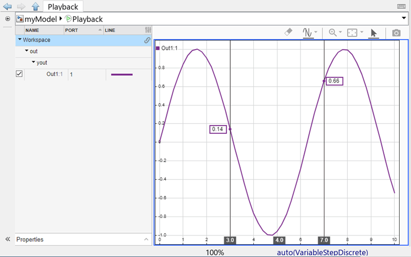
Dashboard panels are virtual dashboards to which you can add blocks from the Dashboard library (including the Customizable blocks library) or the Aerospace Blockset™ library. The panels float above the model canvas and follow you through the model hierarchy. Starting in R2026a, you can add blocks to dashboard panels using the quick insert menu.
To do so, enter edit mode. First, select the panel. Then, in the Simulink Toolstrip, on the Panels tab, click Edit Panels. If needed, resize the panel to make the panel big enough to hold the block you want to add by dragging the panel edges outward. Adding blocks that are bigger than the panel is not supported.
To add the block, double-click where you want to add the block. You must click a blank space on the panel. The quick insert menu appears. Start entering the name of the block you want to add. Select the block you want to add in the list of search results. The new block appears in the panel.
For more information about dashboard panels, see Getting Started with Dashboard Panels.
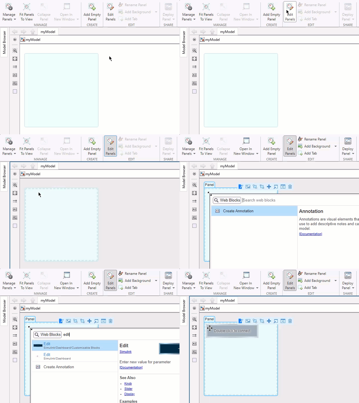
Use the customizable Edit block to change parameter or variable values
The Edit block connects to a parameter or variable value in your model. You can change the connected value before or during simulation by entering a new value in the edit box. When you use the version of the Edit block in the Customizable Blocks library, you can customize the appearance of the block to look like an edit box in an existing digital interface.
Choose from a list of WYSIWYG (what you see is what you get) fonts that look the same on all platforms.
Change the font size.
Change the text color.
Make the text bold, italic, or underlined.
Change the text position within the block.
Add a background image or choose a background color.
Add a foreground image.
Use the Edit block with other dashboard blocks to build an interactive dashboard of controls and indicators for your model.

![]()
Programmatically switch dashboard panel tabs
Dashboard panels can have multiple tabs. You can now programmatically switch which tab a
panel displays using the simulink.dashboard.switchPanelTab function. For example, you can use this
capability to create a dashboard that switches tabs when you click a button by entering the
simulink.dashbaord.switchPanelTab function in the callback function
that runs when you click the button.
simulink.dashboard.switchPanelTab(model,tab)
model is the handle or name of the top-level model containing the tab to
which you want to switch. Specify the handle as a scalar, and the name as a string or
character array. For information about how to get a model handle, see Get Handles and Paths.
tab is the name of the tab to which you want to switch, specified as
a string or character array. To use the
simulink.dashbaord.switchPanelTab function, the model you specify
in the input arguments must be open. Loading the model is not sufficient.
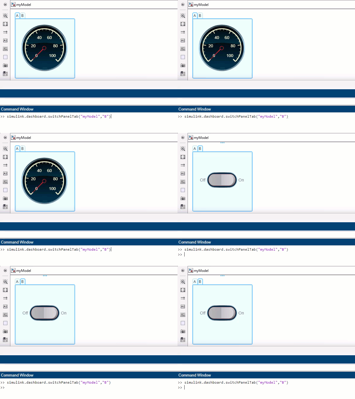
Programmatically check whether a block is a dashboard block
Dashboard blocks are blocks from these libraries:
Dashboard library (including the Customizable Blocks sublibrary)
Aerospace Blockset library
You can now programmatically check whether a block is a dashboard block using the simulink.dashboard.isDashboardBlock function.
tf = simulink.dashboard.isDashboardBlock(block)
block is the block handle or block path. For information about how to
get a block handle or path, see Get Handles and Paths.
If the block is a dashboard block, the function outputs 1. If not, the
function outputs 0.
Use bulk clipboard operations on mask parameters
Starting in R2026a, you can select multiple parameters from Mask Editor and use keyboard shortcuts or mouse pointers for clipboard operations. You can use bulk clipboard operations within the same mask or across multiple masks, which is helpful when you deal with large scale mask definitions. Bulk clipboard operations preserve the properties of the mask parameters, such as constraints and default values. Simulink retains callbacks associated with the mask parameter, if you save them within the mask. However, Simulink does not retain callbacks when you save them in a separate callback file.
Mask Editor: Enhanced constraint manager user interface to manage constraints
Starting in R2026a, you can define and manage all types of parameter and port constraints by using the enhanced Constraints tab in Mask Editor.
Enhancements to the Constraints tab include:
Add all types of parameter and port constraints from the Constraint Gallery panel on the left side of the Constraints tab instead of selecting the constraint type from the toolstrip.
Simulink displays predefined constraints, called as Commonly Used Constraints, in the Constraint Browser panel. You can associate these constraints with mask parameters without creating them manually.
To avoid unintended changes, shared constraint files are locked. To modify a shared constraint file, click Edit File on the toolstrip.
Associate parameters and ports to their respective constraints by using the Associations section of the Constraints tab. Previously, you associated constraints to parameters from the Parameters and Dialog tab.
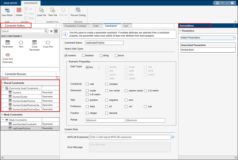
For more information, see Author Parameter and Port Constraints Using Standalone Constraint Manager.
MATLAB System properties are validated in the mask dialog box when focus moved to another control
MATLAB System properties with validation functions such as mustBeNonpositive and mustBeMember are validated in the mask dialog box of a MATLAB
System block when focus is moved to another control.
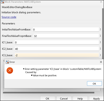
Use fully qualified name to invoke custom functions in a mask callback file
When you save a mask callback file with a model, use the fully qualified names to invoke
custom functions. If the callback file resides in a folder within the model, to avoid
path-related errors, reference the function with its full path. For example, if the name of
the model is engine.slx, the mask callback is
vehicles.m, and the custom function name is
calculateForce, then invoke the function as
engine.vehicles.calculateForce() in the mask callback file.
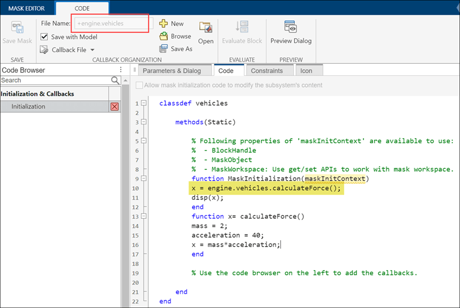
Enhancements to Graphical Icon Editor
Graphical Icon Editor has these enhancements:
Default authoring mode for block icons — Graphical Icon Editor is now the default authoring mode to design masked block icons. To switch to mask drawing commands, in the Authoring Mode section of the toolstrip, click Graphical and then select Drawing Commands.
Customize shape of block frame — To customize the
shape of the block frame, in the Icon Properties pane go to
the Transform section, and select a shape from the
Frame list. Click
to modify the frame as desired and then click close
button. Preview the icon in Simulink to view the modified block frame.
Quick insert element shapes — Search for and insert shapes on the canvas. Double-click the icon canvas and type the name of a shape. A drop-down list of available shapes appears in the drop-down list. Select a shape from the list to insert it into the canvas. Alternatively, in the Tools pane, select Shape Finder to search and insert shapes.
Add port labels to block icons — To specify a port label, in Tools pane, select Port Label.
Properties pane enhancements — Updates to the Icon Properties, Element Properties and Text Properties panes make it easier to navigate and set various properties. You can also automatically generate port labels and associate parameters and expressions with text elements.
For more information, see Graphical Icon Editor Overview.
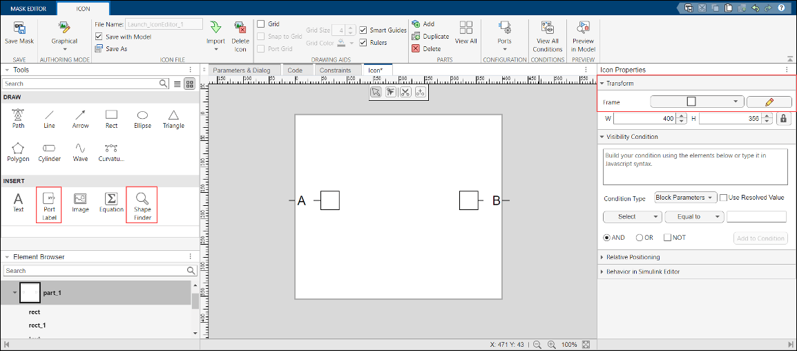
![]()
Define block mask type in a MATLAB System class
Starting in R2026a, you can use the Type property of matlab.system.display.Header class to specify the type of block mask in a
MATLAB System class. The type property helps you to identify blocks having a specific
mask type within a model.
For example, you can set the mask type of a block to Aero and filter
blocks having mask type set as Aero. For more information, see matlab.system.display.Header.
Display mask parameters in a nested structure using the Parameter Tree container
Use the Parameter Tree container in the Mask Editor to display mask parameters in a nested structure. The Parameter Tree container supports Group Box containers and Edit, Check Box, Popup, and Combo Box parameters.
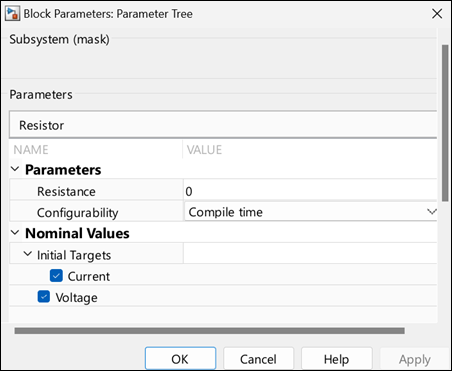
For more information, see Use Mask Containers to Group Parameters on Mask Dialog Box. To programmatically
create and group mask parameters in a parameter tree container, use methods of Simulink.dialog.ParameterTree class.
Associate predefined constraints with mask parameters
Starting in 2026a, Simulink displays predefined constraints in the Constraints tab of the Mask Editor. You can associate these constraints with mask parameters without creating them manually. These constraints are available only for the Parameter Constraint type. The available constraints include:
Numeric
NumericScalar
NumericScalarPositive
NumericScalarPositiveInteger
NumericScalarPositiveZero

The predefined constraints are read-only, and you cannot modify their rules. To associate a constraint with a mask parameter, select the parameter from the Associations section.
For more information, see Use Port Constraints to Validate Input and Output Signals.
Customize custom table parameter in MATLAB System block
To customize a custom table parameter within a MATLAB System block, use the matlab.system.display.Table class in the System object™ class definition file. You can specify the column type as Edit, Popup, or Check
Box. For Popup column type, use the TypeOptions property to
list the Popup options. Additionally, you can set the Evaluate option for
the column to evaluate any MATLAB expression present in the cell.
For more information, see Create Table Parameter for MATLAB System Block.
Banner notification to synchronize System object mask definition XML file
When you modify a MATLAB System class associated with a MATLAB System block, the corresponding mask definition XML file can become outdated. Starting in R2026a, when you modify a MATLAB System class, a notification banner prompts you to open the Mask Editor and perform Save Mask. This action updates the mask definition in the XML file.

Functionality being removed or changed
Adding Signal Builder block warns
Warns
The Signal Builder block is no longer recommended. Adding the Signal Builder block to a model now returns a warning:
Warning: Signal Builder block will be removed in a future release.
Old lookup table blocks being removed
The obsolete versions of these blocks will be removed in a future release. Use the listed replacement blocks instead.
| Obsolete Block | Replacement Block |
|---|---|
PreLookup Index Search | |
Interpolation (n-D) Using PreLookup | |
Lookup Table | |
Lookup Table (2-D) |
Existing models will continue to run until removal.
S-Function blocks will no longer support non-contiguous inputs
Still runs
Starting in R2026a, S-Function blocks support only contiguous inputs. Contiguous input
functions provide faster access and improved performance by removing the need for a double
pointer to access signals. It is recommended to use the ssSetInputPortRequiredContiguous function to specify input signal type and
then access input signals by using the contiguous input functions ssGetInputPortSignal and ssGetInputPortRealSignal instead of ssGetInputPortSignalPtrs and ssGetInputPortRealSignalPtrs, respectively.
Three Dashboard library blocks will be replaced with equivalents from Customizable Blocks library
Behavior change in future release
The Rocker Switch, Slider Switch, and Toggle Switch blocks in the Dashboard library will be replaced with their more customizable equivalents from the Customizable Blocks library in a future release. The new blocks will look the same as the blocks they replace and behave the same in the model. The options for configuring and customizing the blocks will change. The block types will also change.
Block Parameters dialog box table for connecting dashboard blocks will be removed
Still runs
In a future release, connecting blocks from the Dashboard library or the Customizable Blocks library using the table in the Block Parameters dialog box will no longer be supported. Use connect mode instead. For information about connect mode, see Connect Dashboard Blocks to Simulink Model.
Imported and exported type handling in C Function block
Behavior change
Imported type handling — Starting in R2026a, if you do not have a header file available with simulation-compatible type definitions for imported enumerated, bus, or alias types, the block cannot resolve these types and issues an error. To resolve this error, select the Imported type headers are not available for simulation parameter in the C Function block dialog box.
Previously, if the C Function block could not find type definitions for enumerated, bus, or alias types, the block would automatically generate the type definitions for simulation purposes.
Exported type handling — Starting in R2026a, if you specify header files containing type definitions for enumerated, bus, alias types for simulation while that type is exported, you might receive a parser error indicating that the types are already defined. To resolve this error, select the Exported types are defined in simulation custom code headers parameter in the C Function block dialog box.
Previously, if the C Function block was able to find the type definition for enumerated, bus, or alias types, the block did not regenerate type definitions for simulation.
Support model referencing for driver blocks on Arduino hardware
Starting R2026a, you can use all the driver blocks from Simulink Support Package for Arduino® Hardware library inside a model reference. A model reference is a reference to another model using a Model block. These references create model hierarchy and each referenced model has a defined interface that specifies the properties of its inputs and outputs.
For more information on how to use model referencing with Arduino driver blocks in Simulink, see Model Reference Support for Arduino Driver Blocks in Simulink.
Detect state of touch pins on Arduino-compatible ESP32 hardware
This release introduces the ESP32 Touch Sense block for Simulink Support Package for Arduino Hardware. You can use the built-in 10-channel capacitive touch sensor module on the ESP32 board to sense the state of capacitive touch pins on Arduino-compatible ESP32 WROOM and WROVER boards. The block also provides a raw sensor value that represents the capacitance value at the pin you touch.
For more information on capturing images using the ArduCam OV2640 camera module with Arduino-compatible ESP32 hardware, see Capture Images with Touch Sense Using ArduCam OV2640 Camera Module and Arduino Compatible ESP32 Hardware.
Support for handling serial interrupt on Arduino SAMD hardware
Starting R2026a, Simulink Support Package for Arduino Hardware supports handling serial interrupts for the SAMD family of Arduino hardware. The support package introduces Serial Receive and Serial Transmit blocks that supports serial communication interface (SERCOM) interrupt handler. You can access these new blocks from the Advanced > SAMD library.
For more information on configuring SERCOM properties, see Sercom properties. For more information on implementing motor speed control using IMU data and SERCOM serial interrupts on Arduino, see IMU-Based Motor Speed Control on Arduino Using SERCOM Serial Interrupts.
Support added for ThingSpeak and MQTT on Arduino UNO R4 Wi-Fi hardware
Starting R2026a, Simulink Support Package for Arduino Hardware supports deploying a Simulink model containing these blocks on Arduino UNO R4 Wi-Fi® board:
Support added for built-in LED Matrix on Arduino UNO R4 Wi-Fi hardware
Starting R2026a, Simulink Support Package for Arduino Hardware introduces the 12x8 LED Matrix block to configure and control the 12x8 built-in LED matrix on Arduino UNO R4 Wi-Fi board. You can use this block to display graphics. To create a frame to illuminate a target pixel on the built-in LED, use the 12x8 Matrix block and check individual check boxes.
Support added for BLE on Arduino UNO R4 Wi-Fi and Nano RP2040 Connect hardware
Starting R2026a, Simulink Support Package for Arduino Hardware supports deploying a Simulink model containing BLE Send and BLE Receive blocks on Arduino UNO R4 Wi-Fi and Nano RP2040 Connect boards. You can now send and receive data using the Bluetooth® low energy (BLE) protocol on your Arduino UNO R4 Wi-Fi and Nano RP2040 Connect boards.
For more information on configuring BLE properties, see BLE properties.
Support for on-board CAN on Arduino UNO R4 hardware
Starting R2026a, Simulink Support Package for Arduino Hardware supports deploying a Simulink model containing On-board CAN Receive and On-board CAN Transmit blocks on Arduino UNO R4 Wi-Fi and Minima boards.
Support for secure MQTT data communication on Arduino-compatible ESP32 and Raspberry Pi Pico W hardware
Starting R2026a, Simulink Support Package for Arduino Hardware supports establishing a secure MQTT connection between the server and a client using certificate-based authentication. You can now configure MQTT parameters such as specifying an SSL certificate and add a broker client key to authenticate the connection to the server.
For more information on configuring MQTT properties, see MQTT properties.
For more information on securely publishing and subscribing to messages on a Mosquitto™ broker using MQTT blocks on Arduino, see Securely Publish and Subscribe to Messages on Mosquitto Broker Using Arduino Hardware and Generate SSL/TLS Credentials for Mosquitto MQTT Broker.
Identify assumed doubles in MATLAB function report
When you do not specify a size for the output of a MATLAB Function
block, Simulink assumes that input variables have type double during
size propagation. Starting in R2026a, the MATLAB function report identifies these variables by using the indicator
double (assumed). See MATLAB Function Reports. Use this indicator to help you to debug downstream issues in your code. For example,
this indicator can help you to identify if a function passes an assumed double to a
function that does not expect a double. To prevent assumed doubles, explicitly specify
the sizes of all output variables.
Input Argument Validation: Use multiple repeating input arguments in non-entry-point functions
Starting in R2026a, you can use arguments (MATLAB)
blocks in non-entry-point functions that contain multiple repeating input arguments. See
Generate Code for arguments Block That Validates Input and Output Arguments.
In previous releases, MATLAB Function blocks supported only a single repeating input argument to a non-entry-point function.
Use handle classes that have custom copy functionality
Starting in R2026a, MATLAB Function blocks can contain MATLAB functions that use subclasses of the matlab.mixin.Copyable (MATLAB) abstract class. These subclasses inherit:
A public copy (MATLAB) method that makes a
shallow copy of a subclass instance
A protected copyElement (MATLAB) method that you
can override to control the copy behavior of your subclass
MATLAB Function blocks support both the copy and
copyElement methods. MATLAB Function blocks also
support the NonCopyable property attribute, which you can use to
indicate that you do not want to copy a particular property value. See Implement Copy for Handle Classes (MATLAB).
Code generation for more MATLAB functions
Code generation for more toolbox functions
In R2026a, you can generate code for additional toolbox functions and objects. For a list of all functions and objects that are supported for code generation, see:
These are links to the release notes of some toolboxes that added code generation support in R2026a:
Starting in R2026a, you can use the new coder.findOrError function to find the indices and values of nonzero
elements in an array. Unlike the find function that always returns
variable-length vectors in code generation, the
coder.findOrError(X,n) function call returns vectors of fixed
length n if n is a constant during code
generation. If the array X contains fewer than n
nonzero elements, coder.findOrError(X,n) produces either a
compile-time or a run-time error.
See C Code Generation: Generate code from additional functions using MATLAB Coder.
See Deep Learning: Code generation support for inverse short-time Fourier transform.
See:
See Deep Learning: Code generation for continuous wavelet transform.
Functionality being removed or changed
Size propagation errors can occur due to ambiguous variable data types
Errors
As a result of improvements that support additional function
use in the MATLAB Function block, if your output variables inherit
their data type, the block can generate an error during size propagation. To resolve
this error, explicitly define the variable data type. Set the
Type property to a value other than Inherit:
Same as Simulink.
Changes to generation and placement of included header files for models that contain blocks that call functions that specify header file inclusions
Behavior change
Starting in R2026a, when a model includes a MATLAB Function block,
MATLAB System block, or MATLAB function in a Stateflow® chart that calls the coder.cinclude or
coder.ceval function to specify header files, the code generator no
longer includes the specified header files in these locations:
By default, in the generated header file .model.h
In the generated header or source file for a subsystem, unless the call to coder.cinclude or coder.ceval is in that subsystem.
Previously, when a MATLAB function called coder.cinclude or coder.ceval from within a model, the header file #include statements in the generated code included header files specified in the function call, which could lead to unnecessary header file inclusions and cause compilation issues.
For more information, see Integrate C Code by Using the MATLAB Function Block and Model Configuration Parameters: Code Generation Custom Code (Simulink Coder).