Check Dynamic Upper Bound
Check that one signal is always greater than another signal
Libraries:
Simulink /
Model Verification
HDL Coder /
Model Verification
Description
The Check Dynamic Upper Bound block checks if the reference signal,
max, is greater than the amplitude of an input signal,
u, at each time step and executes an assertion after
comparison. If max is greater than u, the
assertion is true (1) and the block does nothing. If not, the block
halts the simulation and returns an error message by default.
The input signals can be scalars, vectors, or matrices. Both input signals must be the same data type. The block compares the value of u to max differently depending on the signal.
When comparing scalars to vectors or matrices, the block compares the scalar signal to each element of the non-scalar signal.
When comparing a vector or matrix signal to another vector or matrix signal, the block checks the signals element-by-element.
For models with an input signal and bound that are both vectors or matrices, the input signal and bound must have the same dimensions.
Examples
Using the Check Dynamic Upper Bound block, you can check if an input signal rises above a changing upper bound during a simulation.
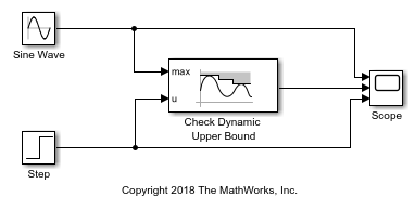
In this example, the Check Dynamic Upper Bound block compares the value of a tested input signal from a Step block at the u port to a Sine Wave block at the max port. The Check Dynamic Upper Bound block checks if the value of the signal at the max port is greater than the value of the tested input signal. If it is, the block asserts true (1). Because the Output assertion signal parameter of the Check Dynamic Upper Bound block is selected, the block outputs the assertion value. Run the simulation to observe the model output.
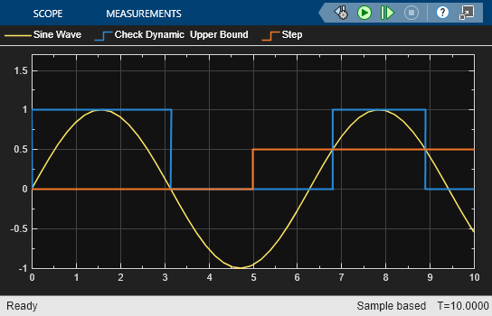
At the start of the simulation, the Check Dynamic Upper Bound block outputs 1 because the value of the Sine Wave block is greater than the value of the Step block. At a time of 3.14, the sine wave dips below 0, causing the value of the Step block to exceed the sine wave. The Check Dynamic Upper Bound block recognizes this change and outputs 0.
At a time of 5, the Step block outputs a value of 0.5, which is still greater than the sine wave. The Step block value stays greater than the sine wave until the time reaches 6.81. The Check Dynamic Upper Bound block recognizes this change and the assertion passes. The output stays at 1 until the time reaches 8.90, where the sine wave goes below the value of the Step block.
Ports
Input
Output
Parameters
Block Characteristics
Data Types |
|
Direct Feedthrough |
|
Multidimensional Signals |
|
Variable-Size Signals |
|
Zero-Crossing Detection |
|
Extended Capabilities
Version History
Introduced before R2006a