Sensorless Field-Oriented Control of PMSM Motor Using Teensy Hardware
R2026bThis example shows how to use Simulink® Support Package for Arduino® Hardware to implement a sensorless field-oriented control (FOC) of a permanent magnet synchronous motor (PMSM). The example deploys the control algorithm to a Teensy development board and drives the motor through the DRV8305EVM inverter.
The example uses an extended electromotive force (EEMF) observer to estimate rotor position and speed, eliminating the need for a physical position sensor. The motor initially runs in open-loop control using the current-to-frequency (I-F) control algorithm. After the EEMF observer starts tracking rotor position, the controller transitions to closed-loop FOC and uses the estimated values for motor control.
Prerequisites
Complete these examples.
Required Hardware
To run this example, you need the following hardware:
Teensy hardware board
TI-Motor Bridge Driver BOOSTXL-DRV8305EVM
Teknic 2310P PMSM motor
24-V DC supply
Connecting wires
Hardware Setup
Connect a 24-V DC supply source to the supply header of the DRV8305EVM driver.
Connect the PMSM motor to the motor header of the DRV8305EVM driver.
Use the connections specified in this table to connect Teensy development board and DRV8305EVM driver.

Configure Motor and Inverter Parameters
Run the arduinoSensorlessPmsmFocSetup script provided with the example.
The script is pre-configured for the Teknic 2310P PMSM motor and defines the PWM timing, ADC offset, motor and inverter parameters, observer parameters for sensorless FOC, target hardware settings, and per-unit (PU) system parameters required by the control algorithm. If you are using a different motor, modify the motor parameters in this script to match the specifications of your motor.
Model Description
Open the arduinoMcbFocSensorlessPmsm Simulink model.

The model has five main stages:
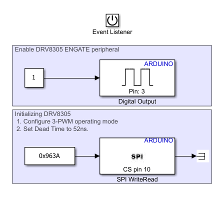
Hardware Initialization — The Initialize Function subsystem enables DRV8305EVM gate driver registers and configures SPI communication. It also configures the motor control hardware and triggers the hardware initialization sequence required for safe motor operation.
ADC interrupt — The Hardware Interrupt block generates a function-call trigger every 50 microseconds, synchronized with the PWM timer. This trigger executes the current control loop at each PWM cycle, enabling accurate current sampling and voltage updates.
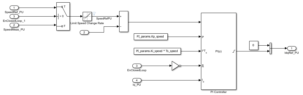
Speed Control — The Speed Control subsystem uses a PI controller to convert the speed error into a q-axis current reference, Idq_Ref. The subsystem limits sudden changes in the speed command to ensure smooth motor acceleration and deceleration. While the motor operates in open-loop I-F mode, it prevents integrator windup. After the controller transitions to closed-loop operation, the subsystem generates the q-axis current reference, Idq_Ref. The FOC controller uses this reference to regulate motor torque and speed.
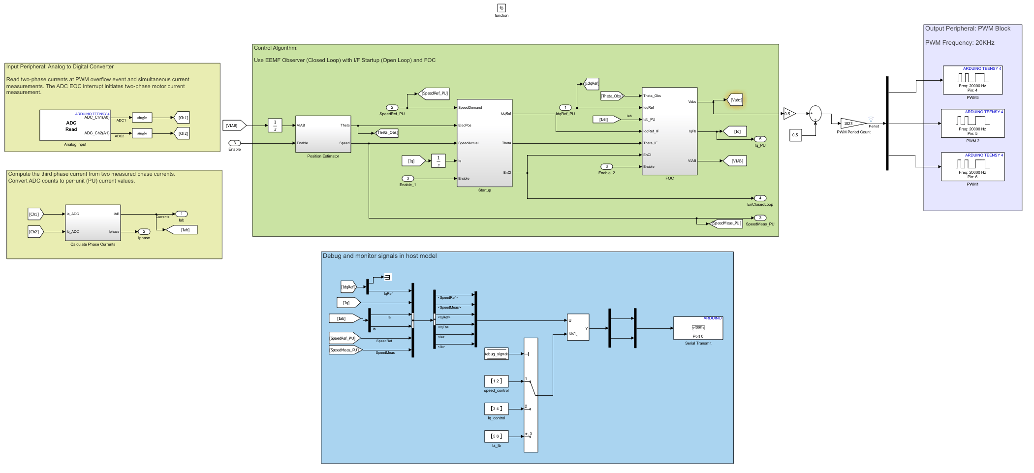
Sensorless FOC and PWM Generation — The ADCTrigger_50us subsystem performs these operations during each interrupt service routine (ISR) execution:
1. The Analog Input block reads the motor phase currents from ADC channel 1 (ISENA) and ADC channel 2 (ISENB).
2. The Calculate Phase Currents subsystem removes calibrated current offsets and converts the raw ADC measurements to phase currents in amperes. The third phase current is reconstructed using Kirchhoff's current law.
3. The Position Estimator subsystem uses an Extended EMF Observer (Motor Control Blockset) to estimate rotor electrical position and speed from the measured voltages and currents.
4. The Startup subsystem uses an I-F Controller (Motor Control Blockset) to start the motor. As the motor accelerates and generates enough back EMF, the observer locks onto the rotor position, and the controller transitions to closed-loop FOC operation.
5. The FOC subsystem implements Field-Oriented Current Controller (Motor Control Blockset) algorithm. It converts three-phase motor currents into a rotating reference frame, regulates them with PI controllers, and outputs PWM duty cycles.
6. The subsystem generates three-phase PWM signals (PWM1, PWM2, and PWM3) for the PMSM motor voltages Vabc and controls their duty cycle.
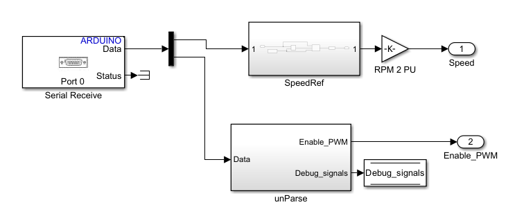
Serial Communication with Host Model — The Serial Receive subsystem implements the communication interface between the host model arduinoHostModelClosedLoopPmsm and the target hardware. It receives speed reference and enable commands from the host computer over the UART0 serial interface and makes them available to the motor control algorithm.
Generate Code and Deploy Model to Target Hardware
This example uses a target model and a host model. The target model runs on the Teensy hardware board and implements the motor control algorithm. The host model runs on the host computer and provides a user interface for monitoring signals and sending commands to the target hardware over serial connection.
1. Complete the hardware connections.
2. Open the target model, arduinoMcbFocSensorlessPmsm.
3. Configure the model for Teensy development board. On the Modeling tab, click Model settings to open the Configuration Parameters dialog box. In the Hardware Implementation pane, set Hardware board to Teensy 4.0 or Teensy 4.1. Click OK.
4. Configure SPI mode. In the Hardware Implementation pane, expand Target hardware resources and select SPI properties. Set SPI mode to Mode 1 - Clock Polarity 0, Clock Phase 1, which is supported by the DRV8305EVM gate driver.

5. Configure baudrate for serial communication. In the Target hardware resources pane, select Serial port properties. Set Serial 0 baud rate to 115200.
6. Deploy the target model to the hardware. On the Hardware tab, in the Mode section, select Run on board.
In the Deploy section, click Build, Deploy & Start.
7. Open the host model, arduinoHostModelClosedLoopPmsm.
8. Select the serial Port in the Host Serial Setup (Motor Control Blockset), Host Serial Receive (Motor Control Blockset), and Host Serial Transmit (Motor Control Blockset) blocks.
9. Specify Baud rate parameter in the Host Serial Setup (Motor Control Blockset) block. The value must match with the value set in step 5.
10. To run the host model, on the Simulation tab, click Run.
11. To start the motor in open-loop I-F mode, set the Motor switch to Start.
12. Increase the Reference Speed in steps until it exceeds the value of Speed to exit I-F controller parameter of the I-F Controller block. The controller then transitions from open-loop I-F control to closed-loop FOC.
13. Monitor motor operation using the scopes and display blocks in the host model. Use the Debug signals section to select the signals to observe. For example, the below figure shows reference speed and measured motor speed.

The motor starts in open-loop I-F mode and transitions to closed-loop sensorless FOC when the EEMF observer acquires rotor position. After the transition, the measured and reference speeds closely match.
See Also
Sensorless Field-Oriented Control of PMSM (Motor Control Blockset)
Host-Target Communication (Motor Control Blockset)
Current Sensor ADC Offset and Position Sensor Calibration (Motor Control Blockset)
Sensorless Field-Oriented Control of PMSM Using I-F Control-Based Startup (Motor Control Blockset)

