Inspect Variable-Size Signals on Simulink Models
Variable-Size Signal Generation and Operations
This example model shows how to create a variable-size signal from multiple fixed-size signals and from a single data signal. It also shows some of the operations you can apply to variable-size signals.
For a complete list of blocks that support variable-size signals, see Simulink Block Support for Variable-Size Signals.
In the MATLAB® Command Window, type
openExample('sldemo_varsize_basic')
varSize = get_param(outPortHandle,'CompiledPortDimensionsMode')
In the Simulink® Editor, on the Debug tab, select Information Overlays > Signal Dimensions. Run a simulation or press Ctrl-D.
The Simulink Editor displays the signal dimensions and line styles. See Signal Basics for an interpretation of signal line styles.
So that you can see the names of the blocks in the model, on the Format tab, clear Auto > Hide Automatic Block Names.
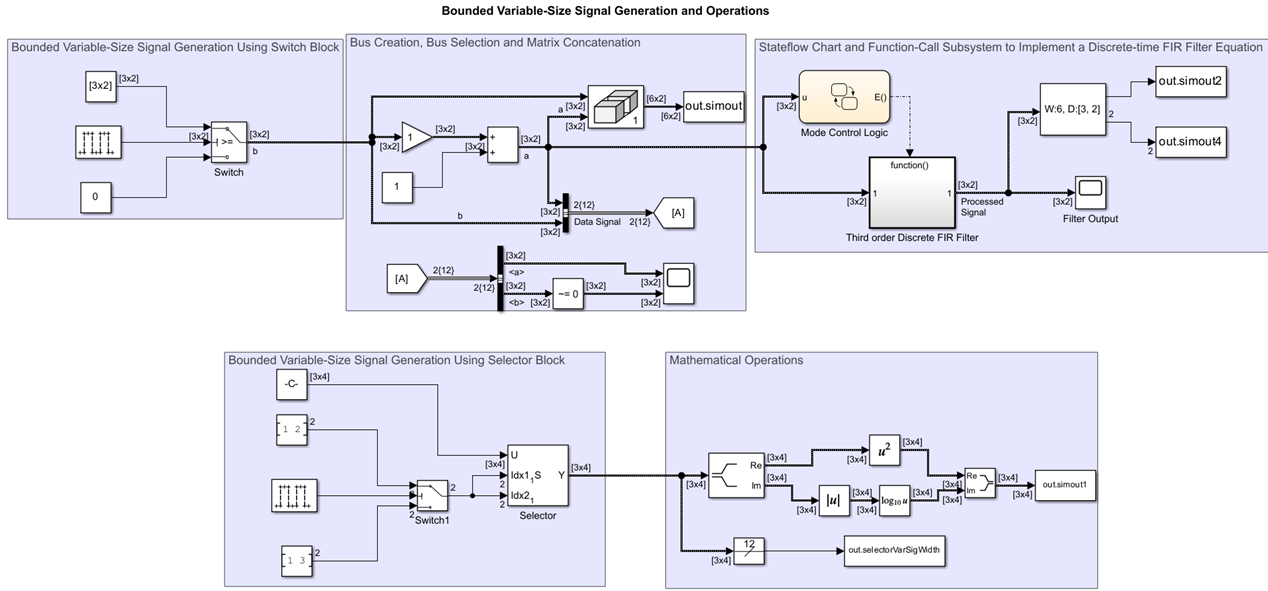
Create a Variable-Size Signal from Fixed-Size Signals
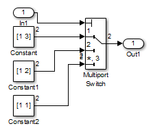
One way to create a variable-size signal is to use the Switch block. The input signals to the Switch block can differ in their number of dimensions and in their size.
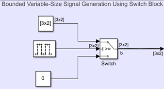
Output from the Switch block is a 2-D variable-size signal with a
maximum size of 3x2. When you select the Allow
different data input sizes parameter on the Switch block,
Simulink does not expand the scalar value from the Constant block
named Constant1.
Save Variable-Size Signal Data
A To Workspace block connected to the output of the Matrix
Concatenate block saves data to a structure named simout. The
values field of the structure array logs the actual signal values. If
logged signal data is smaller than the maximum size, values are padded with NaNs or
appropriate values. To obtain these signal values, type:
out.simout.signals.values

ans(:,:,1) =

     1    -1
    -2     2
    -3     3
     2     0
    -1     3
    -2     4


ans(:,:,2) =

     1    -1
    -2     2
    -3     3
     2     0
    -1     3
    -2     4


ans(:,:,3) =

     0   NaN
     1   NaN
   NaN   NaN
   NaN   NaN
   NaN   NaN
   NaN   NaN


ans(:,:,4) =

     0   NaN
     1   NaN
   NaN   NaN
   NaN   NaN
   NaN   NaN
   NaN   NaN


ans(:,:,5) =

     1    -1
    -2     2
    -3     3
     2     0
    -1     3
    -2     4


ans(:,:,6) =

     1    -1
    -2     2
    -3     3
     2     0
    -1     3
    -2     4


ans(:,:,7) =

     0   NaN
     1   NaN
   NaN   NaN
   NaN   NaN
   NaN   NaN
   NaN   NaN


ans(:,:,8) =

     0   NaN
     1   NaN
   NaN   NaN
   NaN   NaN
   NaN   NaN
   NaN   NaN


ans(:,:,9) =

     1    -1
    -2     2
    -3     3
     2     0
    -1     3
    -2     4


ans(:,:,10) =

     1    -1
    -2     2
    -3     3
     2     0
    -1     3
    -2     4


ans(:,:,11) =

     0   NaN
     1   NaN
   NaN   NaN
   NaN   NaN
   NaN   NaN
   NaN   NaN
The valueDimensions field logs the dimensions of a variable-size
signal. To obtain the dimensions,
type:
out.simout.signals.valueDimensions
The signal dimensions for the first three time steps are shown.
ans =

     6     2
     6     2
     2     1
     2     1
     6     2
     6     2
     2     1
     2     1
     6     2
     6     2
     2     1
Create a Variable-Size Signal from a Single Data Signal
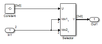
The data signal (Constant5) is a 3x4 matrix. The
Pulse Generator block represents a control signal that selects a starting
and ending index value ( [1 2] or [1 3]). The
Selector block then uses the index values to select different parts of
the data signal at each time step and output a variable-size signal.
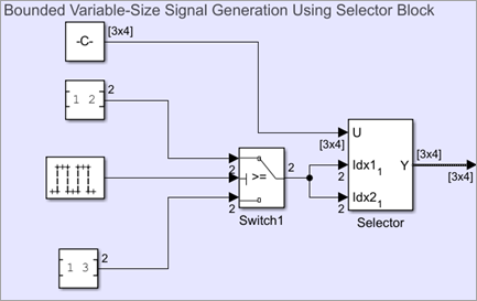
View Changes in Signal Size
The output from the Selector block is either a 2x2
or 3x3 matrix. Because the maximum dimension for a variable-size signal
is the 3x4 matrix from the data signal, the logged output signals are
padded with NaNs.
Use the Probe or Width blocks to inspect the current dimensions and width of a variable-size signal. In addition, you can display variable-size signals on Scope blocks and save variable-size signals to the workspace using the To Workspace block.
Process Variable-Size Signals
The remainder of the model shows various operations that are possible with variable-size signals. Operations include using the Gain, Sum, Math Function, and Matrix Concatenate blocks. You can connect variable-size signals with the From, Goto, Bus Assignment, Bus Creator, and Bus Selector blocks.
Variable-Size Signal Length Adaptation
This example model corresponds to a hypothetical system where the model adapts the length of a signal over time. Length adaptation is based on the value of a control signal. When the control signal falls within one of three predefined ranges, the fixed-size raw data signal changes to a variable-size data signal.
The variable-size signal connects to a processing block, where blocks that support variable-size signals operate on it. A MATLAB Function block with both input and output signals of variable size allow more flexibility than other blocks supporting variable-size signals. See Simulink Block Support for Variable-Size Signals.
To open the example model, in the MATLAB Command Window, type:
openExample('sldemo_varsize_dataLengthAdapt')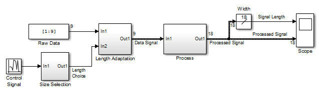
So that you can see the names of the blocks, in the model, on the Format tab, clear Auto > Hide Automatic Block Names.
Creating a Variable-Size Signal by Adapting the Length of a Data Signal
This model generates a data signal and converts the signal to
a variable-size signal. The size of the signal depends on the value
of a control signal. The raw data signal is a column vector with values
from 1 to 9.
[1:9].'

ans =
     1
     2
     3
     4
     5
     6
     7
     8
9Size Selection subsystem determines the quality of the
data signal and outputs a quality value ( 1, 2, or 3). This value helps to select the
length of the data signal in the Length Adaptation subsystem.
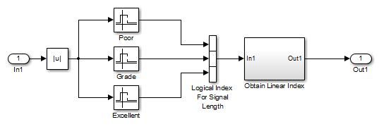
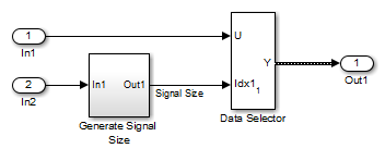
In the Length Adaptation subsystem, the Signal Size
subsystem generates an index based on the quality value from the Size
Selection subsystem (In2). The Data Selector
block uses the starting and ending indices to adapt the length of the data signal
(In1) and output a variable-size signal.
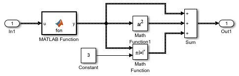
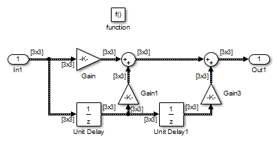
Processing a Variable-Size Signal
The center section of the model processes the variable-size signal. The MATLAB
Function block adds zeros between the data values in a way that is similar to
upsampling a signal. The dimension of the signal changes from 9 to
18. The Math Function blocks show various
manipulations you can do with variable-size signals.
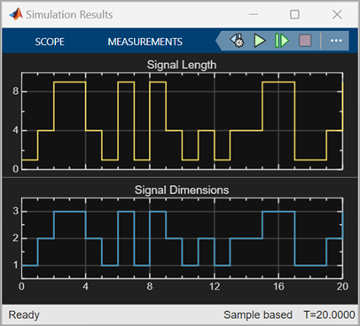
Visualizing a Variable-Size Signal
The right section of the model determines the signal width (size) and uses a scope to visualize the width and the processed data signal.

Mode-Dependent Variable-Size Signals
This example model represents a system that has three operation modes. For each mode, the data signal to process has a different size.
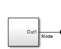
The Process subsystem in this model receives a variable-size signal where
the size of the signal depends on the operation mode of the system. For each mode change,
the Stateflow® chart, Mode Control Logic, detects when the data signal
size changes. It then generates a function call to reset the blocks in the
Process subsystem.
To open the model, In the MATLAB Command Window, type:
openExample('sldemo_varsize_multimode')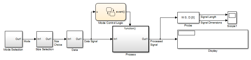
So that you can see the names of the blocks, in the model, on the Format tab, clear Auto > Hide Automatic Block Names.
Creating a Variable-Size Signal Based on Mode
The Mode Selection subsystem determines the mode for processing a data
signal and outputs a mode value (1, 2, or 3). This value helps to select the length of the
data signal using the Size Selection and Data
subsystems.
The Size Selection subsystem creates an index value from the mode value. In
this example, the index values are [1 3], [1 2], and
[1 1].
The Data subsystem takes a data signal (Constant block) and
selects part of the data signal dependent on the mode. The output is a variable-size
signal with a matrix size of 3x3, 2x2, and
1x1.
The dimensions of the raw data signal (Constant block) is a
3x3. After connecting a To Workspace block to a signal
line, you can view the signal in the MATLAB Command Window by typing:
simout.signals.values

ans(:,:,1) =

     1     4     7
     2     5     8
     3     6     9
The variable-size signal generated from the Data subsystem is also a
3x3 matrix. For shorter signals, the matrix is padded with
NaNs.
simout.signals.values

ans(:,:,1) =

     1   NaN   NaN
   NaN   NaN   NaN
   NaN   NaN   NaN


ans(:,:,2) =

     1     4   NaN
     2     5   NaN
   NaN   NaN   NaN


ans(:,:,3) =

     1     4     7
     2     5     8
     3     6     9
Processing a Variable-Size Signal with a Conditionally Executed Subsystem
Because the Process subsystem contains a Delay block, the
subsystem resets and repropagates the signal at each time step. This model uses a
Stateflow chart to detect a signal size change and reset the
Process subsystem.
In the function block dialog box, and from the Propagate sizes of variable-size
signals list, choose Only when enabling. When the
model enables this subsystem, selecting this option directs the Simulink software to propagate sizes for variable-size signals inside the
conditionally executed subsystem. Signal sizes can change only when they transition from
disabled to enabled. For an explanation of handling signal-size changes with blocks
containing states, see How Variable-Size Signals Propagate.
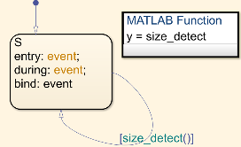
The Stateflow chart determines if there is a change in the size of the signal. The
function size_detect calculates the width of the variable-size signal
at each time step, and compares the current width to the previous width. If there is a
change in signal size, the chart outputs a function-call output event that resets and
repropagates the signal sizes within the Process
subsystem.
Visualizing Data
Use the Probe block to visualize signal size and signal dimension.
Since the signals are n
x n matrices, the signal dimension lines overlap in the
Scope display.
You can use a Display block and the Simulink Debugger to visualize signal values at each time step.
S-Functions Using Variable-Size Signals
Level-2 MATLAB S-Function with Variable-Size Signals
Both level-2 MATLAB S-functions and C S-functions support variable-size signals when you set the
DimensionMode for the output port to
Variable. You also need to consider the current dimension of the
input and output signals in the input and output update methods.
To open this example model, in the MATLAB Command Window, type:
msfcndemo_varsize
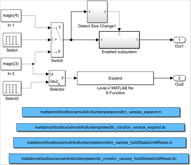
The enabled subsystem includes a Level-2 MATLAB S-Function block which shows how to implement a block that holds its states until reset. Because this block contains states and delays the input signal, the input size can change only when a reset occurs.
The Expand block is a Level-2 MATLAB S-Function block that takes a scalar input and outputs a vector
of length indicated by its input value. The output is by 1:n where
n is the input value.
C S-Function with Variable-Size Signals
To open this example model, in the MATLAB Command Window, type:
sfcndemo_varsize
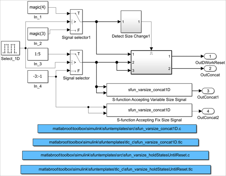
The enabled subsystems have two S-Function blocks:
sfun_varsize_holdStatesUntilResetis a C S-function that has states and requires its DWorks vector to reset whenever the sizes of the input signal changes.sfun_varsize_concat1Dis a C S-function that implements the concatenation of two unoriented vectors. You can use this function within an enabled subsystem by itself.