CAN Input/Output
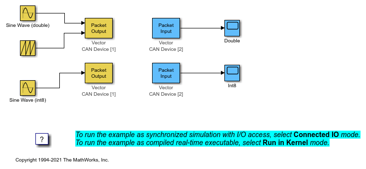
This example shows how to transfer data through CAN bus. The model sends data within one computer, from one CAN channel to another. The two CAN channels can be either virtual channels or physical channels on a dual-channel CAN device. Two different CAN messages using different message identifiers are being transmitted. You can modify the model to communicate between two computers by splitting this model into its send and receive parts and running the models on two computers. The yellow blocks are used to send the data, the blue blocks are used to receive the data.
Note: This model runs on Microsoft® Windows® only.
Run Model in Connected IO Mode
To switch to Connected IO mode if needed, on the Desktop Real-Time tab, select Mode > Connected IO.
To start the real-time execution, on the Simulation tab, click Run.
Run Model in Run in Kernel Mode
To switch to Run in Kernel mode if needed, on the Desktop Real-Time tab, select Mode > Run in Kernel.
To start the real-time execution, click Run in Real Time.
The model builds, connects to Simulink® in Run in Kernel mode, and starts.
Open the Model
These commands open the model and suppress warning about board not installed.
w = warning('off', 'sldrt:blkgui:boardnotonlist');
open_system('sldrtex_canio');
warning(w);
Close Open Scopes
close_system(find_system(gcs ,'BlockType', 'Scope'));
Clean Up Model
clear
close all
bdclose('sldrtex_canio')