Record I/O Data from SoC Device
This example shows you how to record real-world data from hardware for use in simulation.
Supported hardware platforms:
Xilinx® Zynq® ZC706 evaluation kit
Xilinx Zynq UltraScale+™ MPSoC ZCU102 Evaluation Kit
ZedBoard™ Zynq-7000 Development Board
Altera® Cyclone® V SoC development kit
Altera Arria® 10 SoC development kit
In many situations you may want to verify your algorithm against real-world data. This example, using the Streaming Data from Hardware to Software model, shows how to record signals from the AXI4 interface on a SoC device. This workflow allows you to focus on the processor side of the algorithm by substituting a pre-recorded data stream in place of the Simulink® FPGA design.
We recommend completing Streaming Data from Hardware to Software example.

Record Data from FPGA
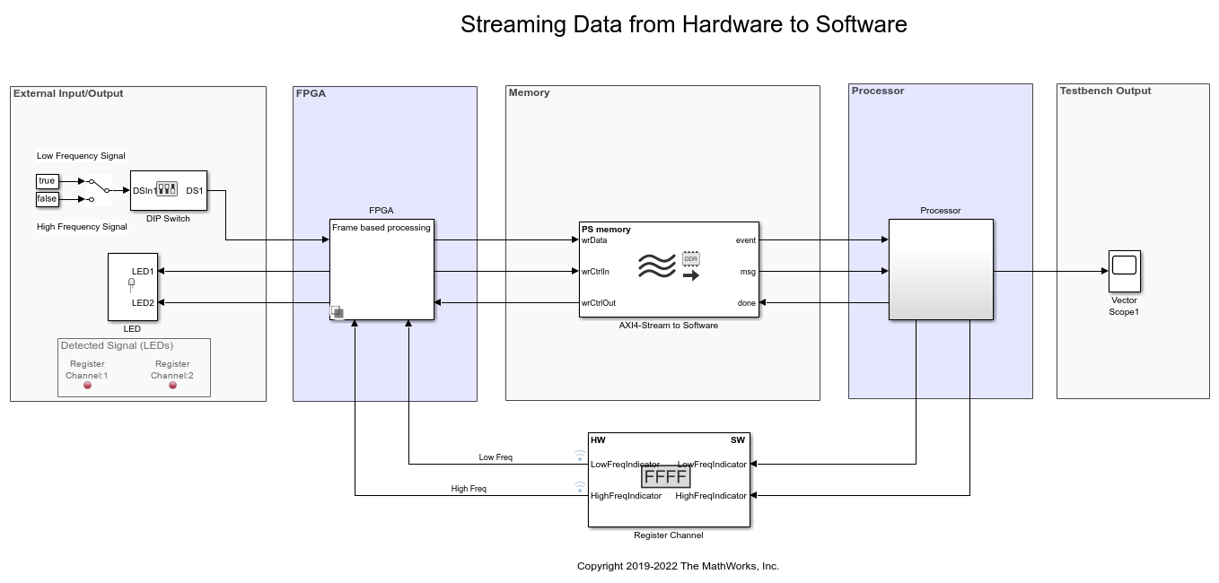
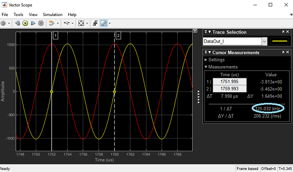
In this section, you will record data generated by the FPGA subsystem in the Streaming Data from Hardware to Software model. In this model, the FPGA subsystem generates a sinusoidal signal with frequency 1kHz or 10kHz, controlled via a DIP switch (DS1). The FPGA algorithm filters the signal and sends it to the processor through AXI4 Stream Memory Channel.

Following products are required for this section:
SoC Blockset™ Support Package for AMD® FPGA and SoC Devices
Follow the steps below to record data from FPGA:
1. Create a hardware communication object executing the following on the MATLAB® command prompt.
hw = socHardwareBoard('Xilinx Zynq UltraScale+ MPSoC ZCU102 Evaluation Kit','hostname','10.10.10.15',...
                      'username','root','password','root')
Enter the appropriate hardware board name, IP address and the user credentials in the command above. The hardware object hw, is a communication gateway that provides control commands and I/O exchange.
2. Open Streaming Data from Hardware to Software model. Load the provided pre-generated FPGA bitstream for this model to hardware.
socLoadExampleBitstream(hw,'soc_hwsw_stream_top')
3. Create a data recorder for your hardware board.
dr = soc.recorder(hw);
4. Create an AXI Stream Read input source object and configure the source properties.
src = soc.iosource(hw,'AXI Stream Read');
src.devName = 'mwfpga_algorithm_wrapper_ip0:s2mm0';
samplingFrequency = 1e5;
src.dataTypeStr = 'uint32';
src.SamplesPerFrame = 1000;
src.SampleTime = src.SamplesPerFrame/samplingFrequency;
The samplingFrequency represents the sine wave sampling rate in the Streaming Data from Hardware to Software model.
5. Add the AXI Stream Read source to the data recording session.
addSource(dr,src,'AXI4 stream interface')
6. Initialize the I/O sources on the hardware board for recording.
setup(dr)
7. Use the record function to record 10 seconds of data.
record(dr, 10)
while isRecording(dr)
    pause (0.1);
end
During the recording, toggle the DIP switch (DS1) to change the frequency of signal generated by the FPGA.
8. Save the recorded data to a file:
save(dr,'sine_wave_data')
Record RF Signals
In this section, you will capture RF signals from an AD - FMCOMMS2/3/4 RF card connected to the FPGA. The data will be streamed from the RF card to the processor using AXI4 stream interface.
Following products are required for this section:
SoC Blockset Support Package for AMD FPGA and SoC Devices
Supported hardware platforms for this section are:
Xilinx Zynq ZC706 evaluation kit
ZedBoard Zynq-7000 Development Board
To configure RF card refer to Set Up AMD FPGA and SoC Devices

1. Open RF Capture model. Load the provided pre-generated FPGA bitstream for this model to hardware.
socLoadExampleBitstream(hw,'soc_rfcapture')
2. Configure radio card.
rf = rfcard(hw);
rf.CenterFrequency = 1090e6;
rf.GainSource = 'AGC Fast Attack';
rf.BasebandSampleRate = 4e6;
rf.ShowAdvancedProperties = true;
rf.ShowInternalProperties = true;
rf.BISTToneMode = 'Tone Inject Rx';
rf();
3. Setup data recorder.
dr = soc.recorder(hw);
src = soc.iosource(hw,'AXI Stream Read');
src.devName = 'mwfpga_data_capture_ip0:s2mm0';
src.dataTypeStr = 'uint32';
src.SamplesPerFrame = 4000;
src.SampleTime = src.SamplesPerFrame/rf.BasebandSampleRate;
addSource(dr,src,'AXI4 stream interface');
4. Record radio signals.
setup(dr)
system(hw,'devmem 0x40010100 32 1');
record(dr,1)
while isRecording(dr)
     pause (0.1);
end
save(dr,'zynq_rf_data')
5. To playback the recorded RF data, open RF Playback model. Enter the dataset name and the source name on the IO Data Source block and simulate the model.

A pre-recorded dataset file zynq_rf_data.tgz is available at matlab\toolbox\soc\socexamples.