Filters
Use these examples to learn how to design signal processing filters to remove or enhance frequency components.
Featured Examples
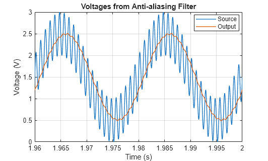
Design Anti-Aliasing Filter for Analog-to-Digital Converters
Design an analog anti-aliasing filter that you can use with an analog-to-digital (A-to-D) converter (ADC). The filter cut-off frequency is 500 Hz, corresponding to the Nyquist frequency which is half the ADC sampling frequency of 1 kHz. The test signal incorporates a desired 50 Hz sinusoid and a higher frequency component at 1100 Hz that you cannot capture with a 1 kHz A-to-D sampling frequency. The scope shows the captured signal with and without anti-aliasing. With the anti-aliasing filter, the ADC correctly measures the 50 Hz sine wave with an amplitude of 1 volt and a DC offset of 1.5 V.
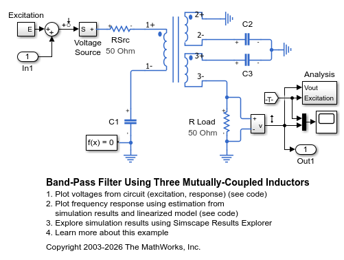
Band-Pass Filter Using Three Mutually-Coupled Inductors
An implementation of a band-pass filter using three mutually-coupled inductors. The model can be used to validate filter parameters which are chosen to provide a band-pass centered on 100MHz. A band-limited noise source is up-shifted by a 100MHz oscillator and applied to the filter. The response is then down-shifted by the oscillator. The model StopFcn callback takes FFTs of the source and response and estimates the filter frequency response.
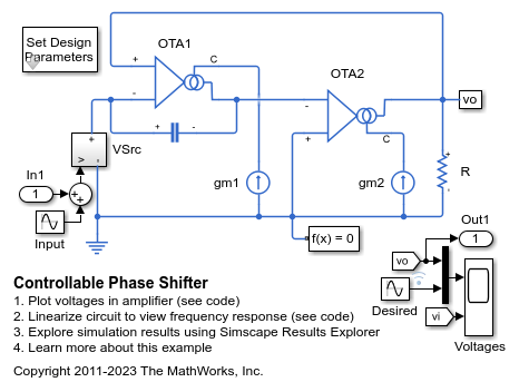
Controllable Phase Shifter
An implementation of a first order phase shifting filter. The filter is characterized by the transfer function H(s) = (sC - gm1)/(sC + gm1). Double-click on the Set Design Parameters block to set the desired phase shift, amplitude of the input signal, and the frequency of the input signal. The block mask calls a function which sets the parameter values in the model workspace.
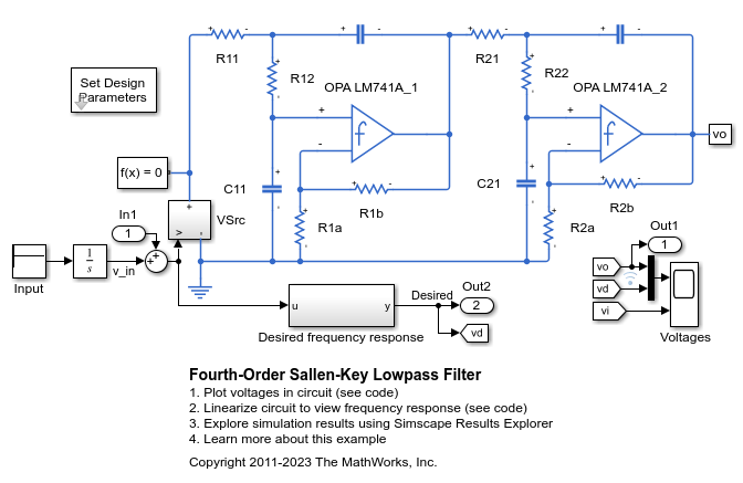
Fourth-Order Sallen-Key Lowpass Filter
An implementation of a fourth-order Sallen-Key low-pass filter using Operational Amplifiers (OPAs). The filter design parameters, cut-off frequency (f1) and DC gain (K), are specified by double-clicking on the Set Design Parameters block. Pass-band ripple is predefined to be 1dB using a Chebyshev response. The block mask calls a function which sets the parameter values in the model workspace.
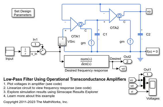
Low-Pass Filter Using Operational Transconductance Amplifiers
Model a second-order active low-pass filter. The filter is characterized by the transfer function H(s) = 1 / ( (s/w1)^2 + (1/Q)*(s/w1) + 1 ) where w1 = 2*pi*f1, f1 is the cut-off frequency and Q is the quality factor. Double-click on the Set Design Parameters block to set parameters f1 and Q. The block mask calls a function which sets the parameter values in the model workspace.