Mutual Inductor
Mutual inductor model with nominal inductance optional tolerances for each winding, operating limits and faults
Libraries:
Simscape /
Electrical /
Passive /
Transformers
Description
The Mutual Inductor block lets you model a mutual inductor (two-winding transformer) with nominal inductance tolerances for each winding. The model includes the following effects:
You can turn these modeling options on and off independently of each other.
In the unfaulted state, the following equations describe the Mutual Inductor block behavior:
where:
v1 and v2 are voltages across the primary and secondary winding, respectively.
L1 and L2 are inductances of the primary and secondary winding.
R1 and R2 are series resistances of the primary and secondary winding.
M is mutual inductance.
k is coefficient of coupling. To reverse one of the winding directions, use a negative value.
t is time.
A parallel conductance is placed across the + and – terminals of the primary and secondary windings, so that iL1 = i1 – G1v1, where G1 is the parallel conductance of the primary winding, and i1 is the terminal current into the primary. Similar definitions and equation apply to iL2.
Do not set the magnitude of the coupling coefficient to values close to 1, such as 0.999, because these values introduce fast simulation dynamics. To set the coefficients of coupling to 1 while also retaining the correct low-frequency behavior, blocking DC, use the Mutual Inductor block in the Simscape Foundation library and select the Perfect coupling – no leakage parameter.
Simscape™ and Simscape Electrical™ libraries include several blocks than can model the same type of transformer device. However, these blocks make different modeling assumptions. To choose the right block for your application, you must understand how these assumptions impact the block behavior as a function of frequency. For more information, see Choose Blocks to Model Transformers.
Tolerances
You can apply tolerances separately for each winding. Datasheets typically provide a tolerance percentage for a given inductor type. Therefore, this value is the same for both windings. The table shows how the block applies tolerances to the nominal inductance value and calculates inductance based on the selected tolerance application option for the winding, L1 tolerance application or L2 tolerance application.
| Option | Inductance Value |
|---|---|
| L |
| Uniform distribution: L · (1 –
tol + 2·
tol·
Gaussian distribution:
L · (1 + tol
· |
| L · (1 + tol ) |
| L · (1 – tol ) |
In the table:
L is nominal inductance for the primary or secondary winding, Inductance L1 or Inductance L2 parameter value.
tol is fractional tolerance, Tolerance (%) /100.
nSigma is the value you provide for the Number of standard deviations for quoted tolerance parameter.
randandrandnare standard MATLAB® functions for generating uniform and normal distribution random numbers.
Note
If you choose the Random tolerance option and you
are in "Fast Restart" mode, the random tolerance value is updated on every
simulation if at least one between the fractional tolerance,
tol, or the Number of standard deviations for
quoted tolerance, nSigma, is set to Run-time
and is defined with a variable (even if you do not modify that variable).
Operating Limits
Inductors are typically rated with a particular saturation current, and possibly with a maximum allowable power dissipation. You can specify operating limits in terms of these values, to generate warnings or errors if the inductor is driven outside its specification.
When an operating limit is exceeded, the block can either generate a warning or stop the simulation with an error. For more information, see the Operating Limits parameters section.
Faults
To model a fault in the Mutual Inductor block, in the Faults section, click Add fault next to the fault that you want to model. For more information about fault modeling, see Fault Behavior Modeling and Fault Triggering.
Instantaneous changes in inductor parameters are unphysical. Therefore, when the Mutual Inductor block enters the faulted state, short-circuit and open-circuit voltages transition to their faulted values over a period of time based on this formula:
CurrentValue =
FaultedValue –
(FaultedValue –
UnfaultedValue) · sech(∆t
/ τ)
where:
∆t is time since the onset of the fault condition.
τ is the value of the Fault transition time constant parameter.
For short-circuit faults, the conductance of the short-circuit path also changes
according to the sech(∆t / τ) function from a small value
(representing an open-circuit path) to a large value.
The Mutual Inductor block lets you select whether the faults occur in the primary or secondary winding. The block models the faulted winding as a faulted inductor. The unfaulted winding is coupled to the faulted winding. As a result, the actual equations involve a total of three coupled windings: two for the faulted winding and one for the unfaulted winding. The coupling between the primary and secondary windings is defined by the Coefficient of coupling parameter.
The block can trigger the start of fault transition:
At a specific time.
After voltage exceeds the maximum permissible value a certain number of times.
When current exceeds the maximum permissible value for longer than a specific time interval.
If you want to trigger a fault at a specific time, in the
Fault Inspector window, set Trigger type to
Timed. If you want to determine whether a system fails and, if
so, when it fails, in the Fault Inspector window, set Trigger
type to Behavioral.
If you select the behavioral trigger, the component fails as soon as one of the trigger conditions is true.
Faultable inductors often require that you use the fixed-step local solver, especially if your model transitions to a faulted state that includes short circuits. For more information, see Making Optimal Solver Choices for Physical Simulation.
Variables
To set the priority and initial target values for the block variables before simulation, use the Initial Targets section in the block dialog box or Property Inspector. For more information, see Set Priority and Initial Target for Block Variables.
Use nominal values to specify the expected magnitude of a variable in a model. Using system scaling based on nominal values increases the simulation robustness. Nominal values can come from different sources. One of these sources is the Nominal Values section in the block dialog box or Property Inspector. For more information, see System Scaling by Nominal Values.
The Primary current and Secondary current variables let you specify a high-priority target for the initial inductor current in the respective winding at the start of simulation.
Examples
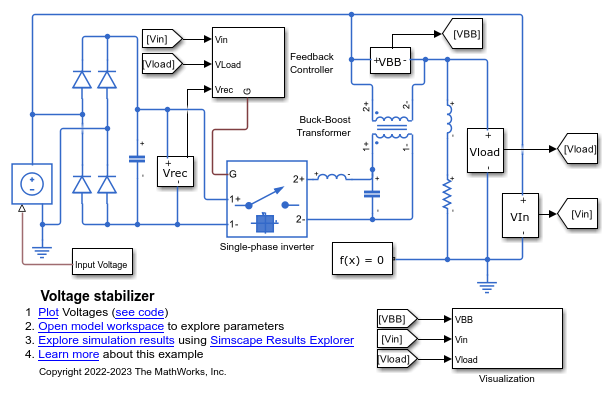
Power Converter Voltage Stabilizer
A voltage stabilizer circuit. It uses a full-wave rectifier, a single-wave inverter, and a buck-boost transformer to achieve voltage regulation.