Transmission Line (Three-Phase)
Three-phase transmission line using lumped-parameter pi-section line model
Libraries:
Simscape /
Electrical /
Passive /
Lines
Description
The Transmission Line (Three-Phase) block models a three-phase transmission line using the lumped-parameter pi-line model. This model takes into account phase resistance, phase self-inductance, line-line mutual inductance and resistance, line-line capacitance, and line-ground capacitance.
To simplify the block-defining equations, Clarke’s transformation is used. The resulting equations are:
where:
R is the line resistance for the segment.
Rm is the mutual resistance for the segment.
L is the line inductance for the segment.
M is the value of the Mutual inductance parameter.
Cg is the line-ground capacitance for the segment.
Cl is the line-line capacitance for the segment.
T is the Clarke’s transformation matrix.
I1 is the three-phase current flowing into the
~1port.I2 is the three-phase current flowing into the
~2port.V1 is the three-phase voltage at the
~1port.V2 is the three-phase voltage at the
~2port.
The positive and zero-sequence parameters are defined by the diagonal terms in the transformed equations:
Rearranging these equations gives the physical line quantities in terms of positive and zero-sequence parameters:
Alternatively, you can specify the
positive-sequence and zero-sequence parameters directly by setting the
Parameterization parameter to By positive and
zero-sequence parameters. (since R2026a)
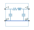
The figure shows the equivalent electrical circuit for a single-segment pi-line model using Clarke’s transformation.
![]()
To increase fidelity, you can use the Number of segments parameter to repeat the pi-section N times, resulting in an N-segment transmission line model. More segments significantly slows down your simulation.
To improve numerical performance, you can add parasitic resistance and conductance components. Choosing large values for these components improves simulation speed but decreases simulation accuracy.
Propagation Speeds
The Transmission Line (Three-Phase) calculates the positive-sequence propagation speeds by using these equations:
is the series impedance, in
Ω/Km.is the shunt admittance, in
s/Km.is the propagation constant.
is the propagation speed, in
Km/s, where .
For zero-sequence propagation speed, the equations are the same but R1, L1, C1, Z1, Y1, γ1, and ν1 are R0, L0, C0, Z0, Y0, γ0, and ν0.
Faults
To model a fault in the Transmission Line (Three-Phase) block, in the Faults section, click Add fault next to the fault that you want to model. For more information about fault modeling, see Fault Behavior Modeling and Fault Triggering.
The Transmission Line (Three-Phase) block allows you to model these types of faults:
Single-phase-to-ground fault (a-g, b-g, or c-g)
Two-phase fault (a-b, b-c, or c-a)
Two-phase-to-ground fault (a-b-g, b-c-g, or c-a-g)
Three-phase fault (a-b-c)
Three-phase-to-ground fault (a-b-c-g)
You can model a fault at one of the two three-phase connection ports, at both connection ports at the same time, or at a specific position along the transmission line.
You specify how and when faults occur by using the Trigger type parameter.
If you set the Trigger type to
Timed, the Transmission Line (Three-Phase) block triggers faults when
the simulation time reaches the value you specify for the Trigger fault at time parameter.
If you set the Trigger
type to Conditional, you can choose
whether faults in the Transmission Line (Three-Phase) block are reversible. To model irreversible
faults, click Open fault properties to open the Property
Inspector and select the Trigger stays on once activated
parameter. The block enters the faulted state when the trigger condition becomes
true for the first time and remains in the faulted state for the rest of the
simulation. To model reversible faults, clear the Trigger stays on
once activated parameter. The block enters the faulted state when
the trigger condition is true and enters the unfaulted state when the trigger
condition is false.
For more information about adding faults to blocks and specifying fault triggers, see Introduction to Simscape Faults.
Examples
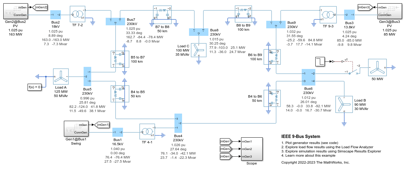
IEEE 9-Bus System
Model a 9-bus three-phase power system network. This example is based on the IEEE® benchmark test case. For more information, see "Power System Control and Stability" by P. M. Anderson and A. A. Fouad (IEEE Press, 2003).
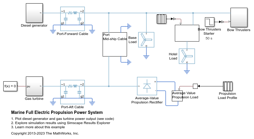
Marine Full Electric Propulsion Power System
A representative marine half-ship electrical power system with base load, hotel load, bow thrusters and electric propulsion.
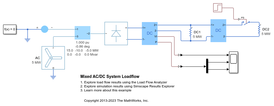
Mixed AC/DC System Loadflow
Use the Load Flow Analyzer to review the load flow results of a mixed AC/DC system. The model to which this analysis is applied includes an AC load flow source, a three-phase rectifier, and three loads. One of the loads is AC, one is permanently connected on the DC side, and one is switched on the DC side.