Model Bang-Bang Temperature Control System
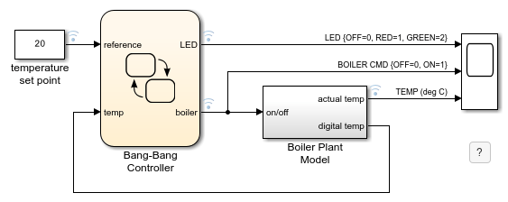
This example shows you how to build a bang-bang control system for boiler temperature regulation. This example demonstrates a bang-bang control system for boiler temperature regulation. The system implements a Stateflow® chart for control and timing, and a Simulink® subsystem to model boiler behavior. The system has two key components:
Bang-Bang Controller:A Stateflow chart that controls heating cycle timing, manages temperature setpoints, and handles state transitions using temporal logic. It uses fixed-point data to represent the boiler temperature.Boiler Plant Model: A Simulink subsystem that simulates real-time temperature dynamics for the boiler under different states.
Control Logic Operation
The Bang-Bang Controller system starts in the Off state and follows a sequence controlled by Stateflow temporal logic. When you initialize the system:
The
Offstate remains active for40seconds.At
40seconds, the controller checks the boiler temperature.If the temperature indicates cold conditions, the controller transitions to the
Onstate.The
Onstate stays active for20seconds.The chart trasitions back to the
Offstate. This60second cycle continues until you stop the simulation.
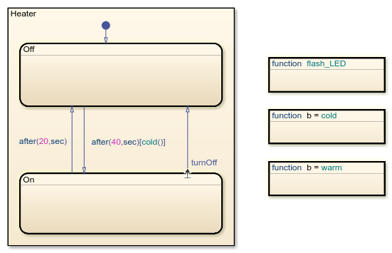
The transitions between the On and Off states are timed by using the after operator. For example, after(20,sec) triggers the transition from On to Off after 20 seconds. The transition label after(40,sec)[cold()] triggers the transition from Off to On if the function cold returns true after 40 seconds.
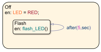
The Off state uses a substate called Flash with a self-loop transition to control a status LED. The transition label after(5,sec) triggers the entry action of the substate and causes the LED to flash every 5 seconds.
Temperature Signal Processing
The Boiler Plant Model subsystem simulates the temperature reaction of the boiler during periods of heating or cooling. Depending on the output of the Bang-Bang Controller chart, the subsystem adds or subtracts +1 for heating or –0.1 for cooling to the previous boiler temperature. The chart then passes the result to the Digital Thermometer subsystem.
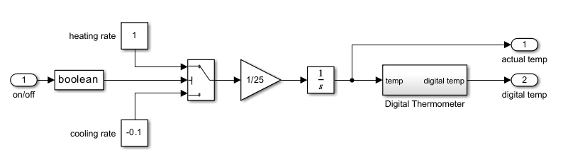
In the Digital Thermometer subsystem the temperature signal passes through three stages that transform temperature readings into digital control values.
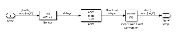
The temperature signal passes through three sequential conversion stages that transform raw temperature readings into digital control values.
The Sensor block converts boiler temperature into analog voltage using linear transformation, which results in a voltage proportional to the temperature.
The Analog-to-Digital Converter block transforms the analog voltage into discrete 8-bit values. The system multiplies the voltage by a conversion factor, rounds the result to the nearest integer, and clamps it to maintain 8-bit boundaries. The output is a quantized integer.
The Linear Fixed-Point Conversion block processes the 8-bit integers into final temperature values. It applies a calibrated slope and a bias offset to generate the digital temperature reading. This maintains compatibility with the 8-bit environment while preserving measurement accuracy.
This system operates within 8-bit parameters: an input range of 0-255, resolution of 1/256 full scale, and fixed-point arithmetic throughout all calculations. This sequence guarantees consistent temperature representation across your entire control system, from sensor input to final control output.
The Bang-Bang Controller chart then receives this digitally coded temperature and interprets it as unsigned 8-bit fixed-point data. The chart processes the temperature data in an 8-bit environment.
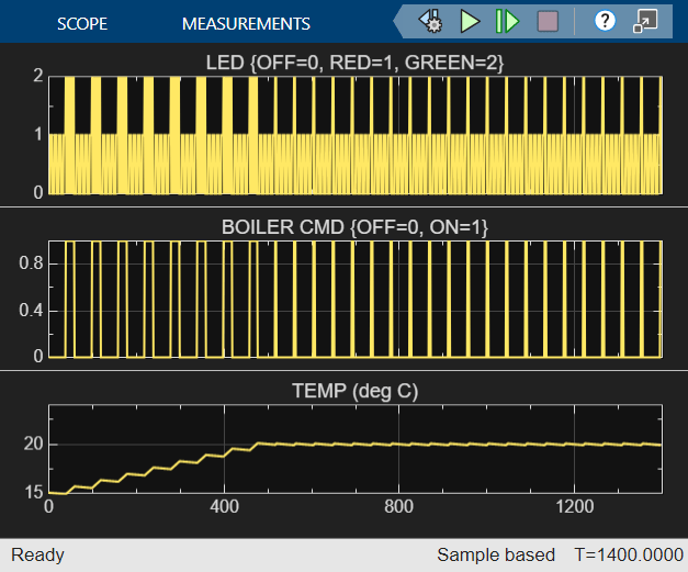
Simulation Results
The simulation results show that the boiler reaches 20°C after 450 seconds (7.5 minutes). The bang-bang controller then maintains this target temperature throughout the remaining runtime.
See Also
after | every | Data Type Conversion (Simulink)