Simulate Asynchronous Services for Vehicle Headlight Management
This example shows how to use asynchronous services to simulate vehicle headlights in a System Composer™ software architecture model.
In this example, the model HeadlightArch consists of a lighting manager component, LightingManager, two headlight components, LeftHeadlight and RightHeadlight, and a component for logging, Logging. The headlight components are modeled as two different instances of the same referenced model, HeadLight.
The referenced model defines two Simulink® Functions:
setMode, which takes in thelightModevariable and returns an output that indicates whether the headlight is brokengetMode, which returns thelightModevariable
A single service interface is specified between the lighting manager and the two headlight instances, which allows the manager to call setMode or getMode for a specific instance of the referenced headlight component.
Open the model.
model = systemcomposer.openModel("HeadlightArch");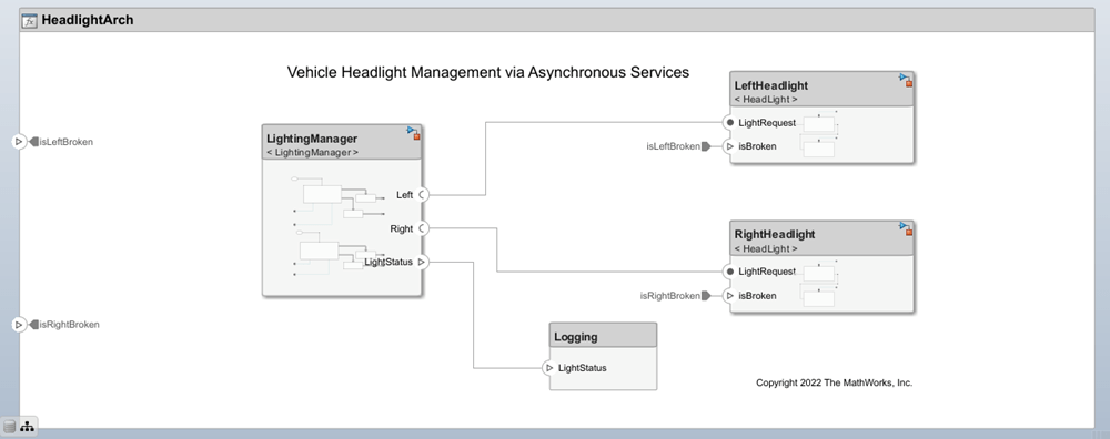
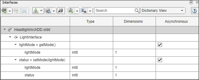
Define Asynchronous Services Using Interface Editor
To view the Interface Editor, on the toolstrip, navigate to Modeling > Interface Editor. Notice that the Asynchronous check box is selected for the function elements representing the functions getMode and setMode.
The block parameters for the Simulink behavior models are pre-configured to support asynchronous simulation.
On the server model, the Trigger block parameter Execute function call asynchronously within the Simulink Function blocks for setMode and getMode is selected. On the client model, the Function Caller block parameter Execute function call asynchronously is selected.
Asynchronous Function Calls for Simulation of Vehicle Headlights
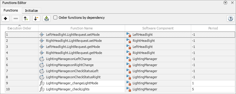
For asynchronous execution, when the client makes a request to the server, the server responds according to the priority order defined in the Functions Editor instead of the order in which the requests were received. To launch the Functions Editor tool, on the toolstrip, go to Modeling > Functions Editor.
Use the Functions Editor tool to change the order of execution of the functions so that when these functions are called at the same time, the higher priority function is executed first.
If a function from the list calls another function:
If a lower priority function is already running, the higher priority function runs. After its completion, the lower priority function continues to run.
If a higher priority function is already running, the lower priority function runs after the higher priority one.
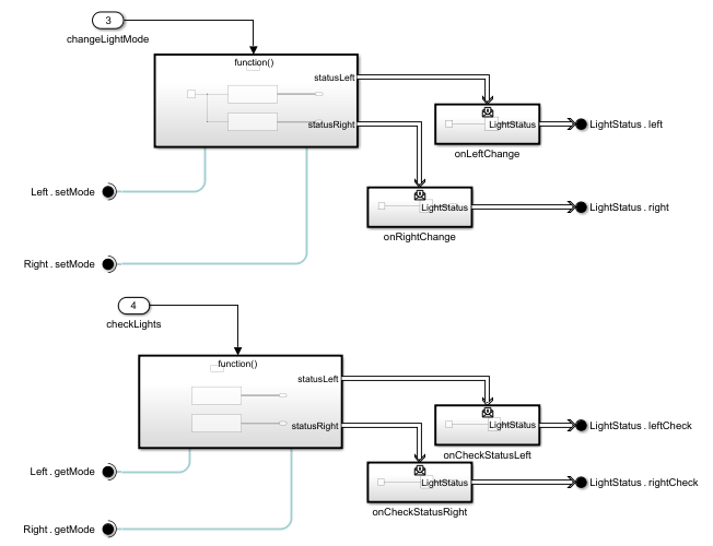
For asynchronous function calls, the Function Caller block has a message output port consistent with the number of output arguments. This message output port connects to a Message Triggered Subsystem block to process the messages. The LightingManager component references the LightingManager Simulink model that consists of two asynchronous function calls. The changelLightMode Function-Call Subsystem block uses the setMode function and determines how each headlight should change its lighting mode. The checkLight Function-Call Subsystem block uses the getMode function and checks whether each headlight is broken and returns its status.
Simulate the model.
sim("HeadlightArch");You can visualize the logged signals after simulation using the Simulation Data Inspector. On the toolstrip, go to Simulation > Data Inspector.
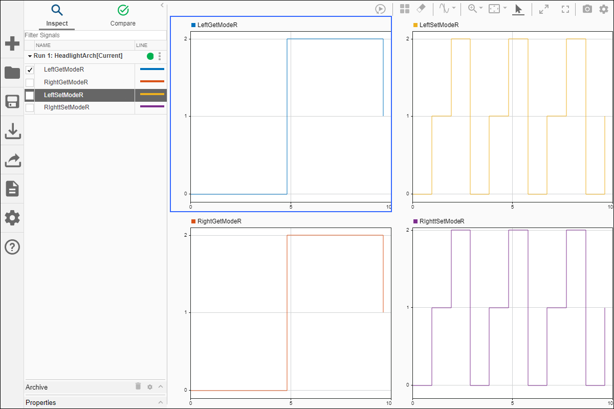
To view the execution order of the function calls, on the toolstrip, launch the Sequence Viewer by navigating to Simulation > Sequence Viewer. Simulate the model again to view the logged messages on the Sequence Viewer and the order in which messages are executed. Since the setMode function is at a higher priority order on the Functions Editor, those server calls are received first.
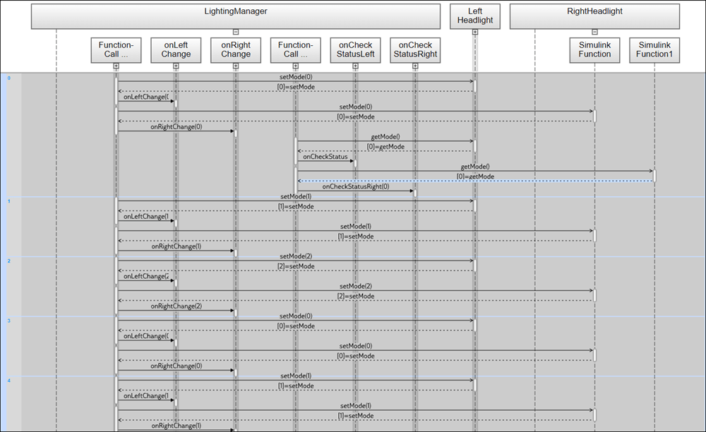
You can change the priority order of the functions in the Functions Editor and view the result in the Sequence Viewer.
See Also
Blocks
- Function Element | Function Element Call | Simulink Function | Function Caller | Function-Call Subsystem | Message Triggered Subsystem