Control Law Accelerator in DC-DC Power Conversion
This example shows how to manage the voltage mode control (VMC) algorithm for a closed loop DC-DC power conversion system by using the Control Law Accelerator (CLA). An auxiliary software current protection loop is managed by C2000 CPU. In the TMS320F28379D and similar processor families, the CLAs execute the hard-realtime portions of the algorithm can connect with hardware peripherals such as ADC's and PWM's. The C2000 CPU is better suited for hard real-time portions of the algorithm that require multitasking, handling of asynchronous events, and communication with other cores. While this example extends the DC-DC buck converter developed in the C2000 DC-DC Buck Converter Using MCU example, the strategy presented can be applied to any design where a resource intensive hard real-time process executes on the CLA and real-time multi-tasking processes run on C2000 CPU.
Required Hardware
TI Delfino F28379D LaunchPad or F28P650D LaunchPad (requires a LaunchPad style passthrough socket strip connector as has been mentioned in Appendix 9.1)
Available Models
TI Delfino F28379D LaunchPad:
System Model: soc_dcdc_pwr_conv.slx
CPU1 Model: soc_dcdc_pwr_conv_c28x_ref.slx
CLA Model: soc_dcdc_pwr_conv_cla_ref.slx
TI F28P650D LaunchPad:
System Model: socDCDCPwrConvF28P65x.slx
CPU1 Model: socDCDCPwrConvF28P65xC28xRef.slx
CLA Model: socDCDCPwrConvF28P65xCLARef.slx
Hardware Connections
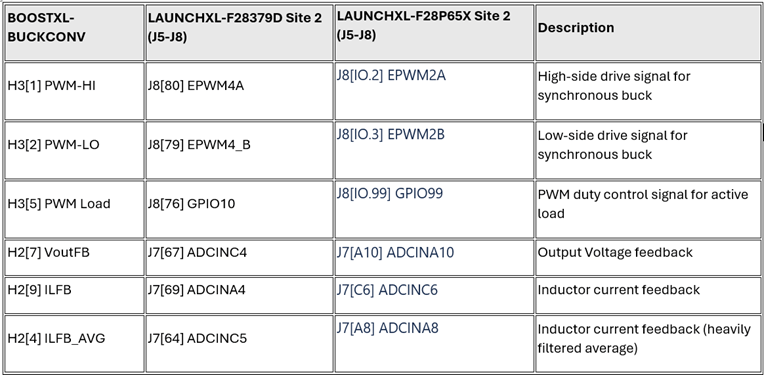
Connect the Digital Power Buck Converter BoosterPack (BOOSTXL-BUCKCONV) to the Texas Instruments Delfino F28379D LaunchPad or the Texas Instruments F28P650D LaunchPad as detailed in the following table.
Voltage Mode Control Algorithm on CLA
This model shows a DC-DC power conversion system with the voltage mode control (VMC) algorithm executing on the CLA. The model assigns a separate Task Manager (SoC Blockset) block to the CLA and C2000 CPU reference models. For more information about scheduling tasks on the CLA, see the CLA Task Manager documentation. Open the model.
open_system('soc_dcdc_pwr_conv');
Top-level model soc_dcdc_pwr_conv does not build by having the Processing Unit parameter to none. In each reference model, set the Processing Unit parameter to a specific processor. On the System on Chip tab, click Hardware Settings to open the Configuration Parameters window.
For the CLA reference model, set Processing Unit to
CPU1CLA1in the Hardware Implementation tab.For the C2000 CPU reference model, set Processing Unit to
c28xCPU1in the Hardware Implementation tab.
Select the appropriate interrupt source for the CLA in the Task Mapper tool. This example uses ADCCINT4 as the ADC interrupt to the CLA. For more information about designing the VMC and peripheral configuration, see C2000 DC-DC Buck Converter Using MCU.
The CLA has restricted regional memory access. Specify the memory sections for inports, outports, signals, states, and internal data by using the Code Mappings Editor — C (Embedded Coder) tool in the CLA reference model. You can ensure that the CLA has appropriate access to these sections by specifying the initialize, execute, and terminate function program spaces. By default, this model has appropriate code mapping for the CLA.
Current Protection Algorithm on C2000 CPU
A current protection algorithm runs on the C2000 CPU. This algorithm monitors the current levels and protects the hardware if the current spikes beyond a set current threshold level. The CLA and the C2000 CPU can access the same peripheral modules. This algorithm is an auxiliary asynchronous component of the power conversion system, the more computationally intensive VMC algorithm on the CLA.
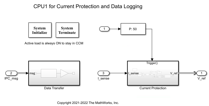
The C2000 CPU sends the voltage reference signal to the CLA and receives and logs the values of current and voltage feedback. The Interprocess Data Channel (SoC Blockset) blocks model the data exchange between the CLA and the C2000 CPU. When deployed to hardware, these blocks utilize a section of shared memory for data transfer between the CLA and the C2000 CPU and ensure data integrity.
Results
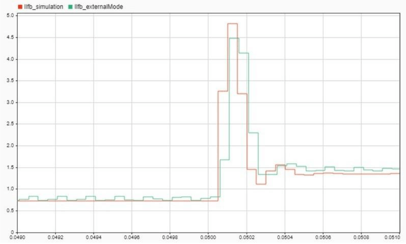
The following graph shows the step response from 0 to 2 volts. The voltage mode controller correctly tracks the desired reference voltage. The currents are below the threshold and the algorithm continues without interruption. It is also observed that the external mode results track the same output obtained in simulation mode.
The following graph shows that when the current exceeds the threshold of 6 amps, the current protection algorithm is triggered. To restore power conversion function functionality, the board must be reset.

When the input is changed from 0 to 3 volts, the current exceeds the threshold of 6 amps and triggers the current protection algorithm.