Fly a Custom Multicopter Airframe Using Simulink
This example shows how to control a custom multicopter airframe by defining a custom mixer matrix in Simulink® and deploying it to ArduPilot® hardware. You will configure motor mixing logic that translates high-level flight commands into individual motor outputs, allowing your multicopter to respond correctly to throttle, roll, pitch, and yaw inputs.
Mixer Matrix Fundamentals
In multicopter systems, a mixer plays a critical role in translating control commands into motor outputs. The mixer is represented as a matrix that transforms the four controller outputs namely throttle, roll, pitch, and yaw into individual PWM values (pulse widths), which are sent to the Electronic Speed Controllers (ESCs) to drive the motors.
The basic relationship between the controller commands and motor outputs is shown here.
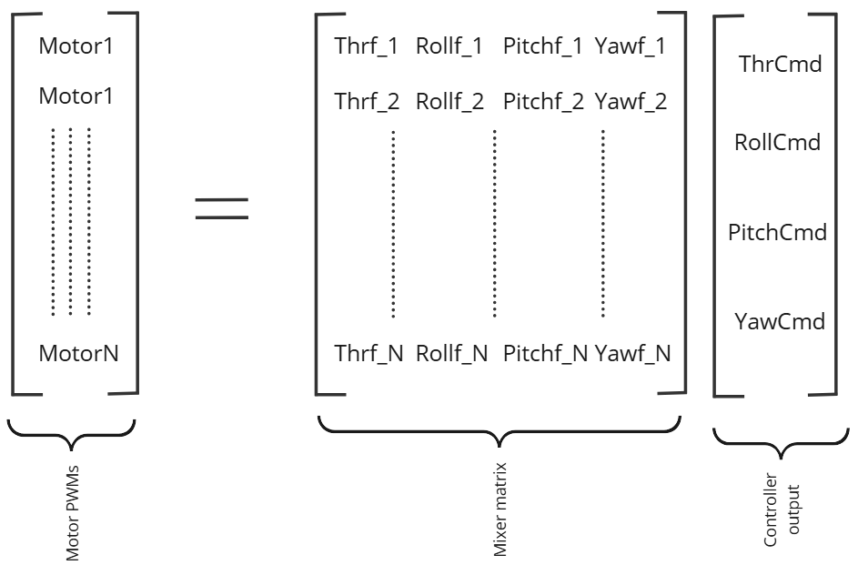
In this equation, Motor1 to MotorN represent the motor actuator outputs (PWM signals sent to each motor). ThrCmd, RollCmd, PitchCmd, and YawCmd are the throttle, roll, pitch, and yaw outputs, respectively, from the controller. The mixer matrix values should be normalized to the range -1 to +1 to ensure consistent scaling across all motor commands.
The mixer matrix is organized with four columns, where each column contains the throttle factor, roll factor, pitch factor, and yaw factor for each motor. These factors determine how much each control input (throttle, roll, pitch, yaw) contributes to the output of each motor.
Roll, Pitch, Yaw, and Throttle Factors
These values are known as control input factors or mixing coefficients. They define how each motor responds to the different control inputs:
Roll Factor – Determines how much a change in the roll command (left/right tilt) affects the speed or position of a specific motor.
Pitch Factor – Determines how much a change in the pitch command (forward/backward tilt) affects the motor output.
Throttle Factor – Determines how much the collective throttle (overall lift or power) affects the motor's output.
Yaw Factor – Determines how much a change in the yaw command (rotation around the vertical axis) contributes to the motor output.
In this example, you will learn how to simulate and fly a multicopter with a custom airframe using Simulink.
Prerequisites
If you are new to Simulink, watch the Simulink Quick Start video.
Complete hardware setup. For more information, see Install UAV Toolbox Support Package for ArduPilot Autopilots in Windows.
Normalize the mixer matrix values to the range
−1to+1. If they are not normalized, divide each column (roll, pitch, yaw, and throttle factors) of the matrix by the highest absolute value in that column.
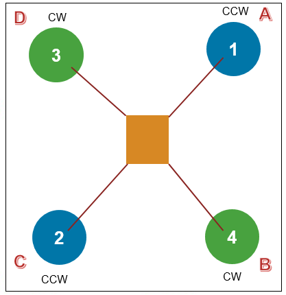
This example uses the Quad/X airframe, an ArduPilot-supported airframe. You can replace the default mixer matrix with your own custom frame's matrix.
Note: This example does not cover the process of calculating or designing a mixer matrix for a custom airframe. If you want to use this workflow with a custom airframe, you must compute the normalized mixer matrix independently beforehand.
Airframe Used in This Example
This example uses the Quad/X airframe, which is supported by ArduPilot. You can replace the default mixer matrix with one that corresponds to your custom airframe.

Running the Model in Host Target
In this task, you will run a custom controller model that uses the mixer matrix of a Quad/X airframe. This example includes the custom mixer feature through the Write Torque & Thrust block in the block library. The custom controller model provides roll, pitch, yaw, and throttle inputs to this block.
Note: In Software-In-The-Loop (SITL) simulations, you cannot fly using a custom airframes because the plant model supports only ArduPilot-approved airframes.
Configure Parameters for Custom Mixer
Before running the model, you need to configure the following ArduPilot parameters to enable support for scripting-based custom mixers.
SCR_ENABLE = 1(Enables Lua scripting engine. This is required even if no Lua script is used in this example.)FRAME_CLASS = 15(Enables scripting-based mixer matrix loading)
Note: If these parameters were already set previously, you do not need to configure them again. However, make sure the values are correct and that no Lua script is currently overriding the mixer matrix.
Perform these steps to configure the parameters.
1. Open a terminal and launch WSL (Windows Subsystem for Linux).
2. Navigate to your ArduPilot directory (the same one used during the hardware setup).
3. Start SITL with MAVProxy by running the following command.
./Tools/autotest/sim_vehicle.py -v ArduCopter --map --console
4. Set the SCR_ENABLE parameter in MAVProxy. Enter the following command in the MAVProxy terminal window:
param set SCR_ENABLE 1
5. Set the FRAME_CLASS parameter in MAVProxy. Enter the following command in the MAVProxy terminal window:
param set FRAME_CLASS 15
Press Ctrl+C to exit SITL after setting the parameters.
Configure the Simulink Model
To simulate and control your custom multicopter using Simulink, you need to configure the model with the appropriate mixer settings and airframe parameters. This section guides you through how to set up the Write Torque & Thrust block, select the correct airframe, and prepare for simulation and testing using Mission Planner.
1. Open the PositionAttitudeControllerCopter example model. The hardware board is already set to Host Target.
modelName = "PositionAttitudeControllerCopter";
open_system(modelName)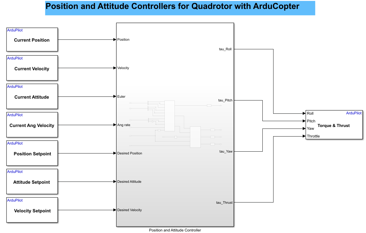
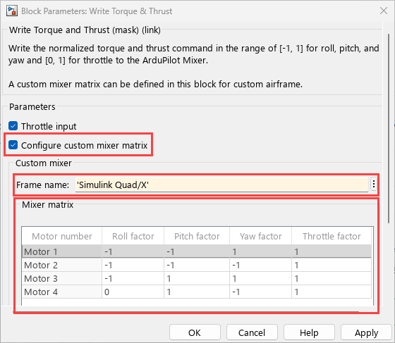
2. In the Write Torque & Thrust block:
Select Configure mixer matrix option.
Enter your custom frame name in the Frame name field. For example, S
imulink Quad/X. The default mixer matrix is for Simulink Quad/Plus. For this example, modify it for Simulink Quad/X.Add or remove motor rows using the table UI.You must include at least 4 motors, and you can add up to 12.
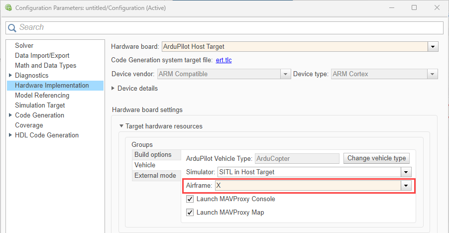
3. In the Configuration Parameters dialog, set the Airframe to X to match the SITL plant.
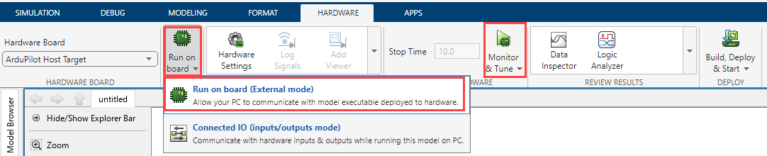
4. Perform Monitor and Tune action for the model.
Go to Hardware tab, and click Monitor & Tune to configure the model for simulation.
5. Open Mission Planner.
It should automatically connect via UDP port 14550 once MAVProxy starts.
If it does not connect automatically, manually connect using port 14550.
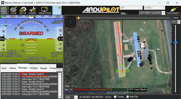
6.In Mission Planner, go to the Messages tab and verify your frame name.
7. Fly the copter. For more information, see Mission Planner Flight Plan.
Once the mission starts, observe the vehicle as it follows the planned mission.
Running the Model on Physical Hardware
You can run the Simulink model on actual hardware by configuring your flight controller and repeating the Simulink configuration steps used for host simulation (excluding SITL-specific steps).
1. Connect the flight controller to Mission Planner. For more information, see Setting Up Communication Between ArduPilot Hardware and Ground Control Station.
2. Go to Config > Full Parameter List and set the following parameters:
SCR_ENABLE = 1FRAME_CLASS = 15
3. Reboot the board to apply the changes.
Note: Although SCR_ENABLE enables Lua scripting, no Lua script is used in this workflow. Ensure that no existing Lua script is modifying the mixer matrix.
4. Configure Simulink Model for Hardware Deployment.
Reuse your custom mixer matrix and airframe settings.
Skip SITL-specific steps. They are not needed when running on hardware.
Other Things to Try
Try executing this example on an actual hardware.
Try with your own custom airframe by replacing the mixer matrix.
Experiment with different control strategies in the custom controller.
Try using motor test in Mission Planner.