Main Content

rectifyStereoImages

Rectify pair of stereo images

Description

example

[J1,J2,reprojectionMatrix] = rectifyStereoImages(I1,I2,stereoParams) undistorts and rectifies versions of I1 and I2 input images using the stereo parameters of a stereo camera system stored in the stereoParams object. Use the reconstructScene function with the reprojectionMatrix to reproject a 2-D point in a disparity map to a 3-D point in the rectified camera coordinate system of camera 1.

Stereo image rectification projects images onto a common image plane in such a way that the corresponding points have the same row coordinates. This image projection makes the image appear as though the two cameras are parallel. Use the disparityBM or disparitySGM functions to compute a disparity map from the rectified images for 3-D scene reconstruction.

[___,camMatrix1,camMatrix2,R1,R2] = rectifyStereoImages(I1,I2,stereoParams) returns the 3-by-4 camera projection matrices camMatrix1 and camMatrix2 for the rectified cameras, and the corresponding rectification rotation matrices, R1 and R2.

[J1,J2] = rectifyStereoImages(I1,I2,tform1,tform2) returns rectified versions of I1 and I2 input images by applying projective transformations tform1 and tform2.

example

[J1,J2] = rectifyStereoImages(___,interp) additionally specifies the interpolation method to use for rectified images. You can specify the method as "nearest", "linear", or "cubic".

example

[J1,J2] = rectifyStereoImages(___,Name=Value) specifies options using one or more name-value arguments in addition to any combination of arguments from previous syntaxes. For example, OutputView="valid" sets the OutputView argument to "valid".

Examples

collapse all

Specify images containing a checkerboard for calibration.

imageDir = fullfile(toolboxdir('vision'),'visiondata', ...
    'calibration','stereo');
leftImages = imageDatastore(fullfile(imageDir,'left'));
rightImages = imageDatastore(fullfile(imageDir,'right'));

Detect the checkerboards.

[imagePoints,boardSize] = detectCheckerboardPoints(...
    leftImages.Files,rightImages.Files);

Specify world coordinates of checkerboard keypoints.

squareSizeInMillimeters = 108;
worldPoints = generateCheckerboardPoints(boardSize,squareSizeInMillimeters);

Read in the images.

I1 = readimage(leftImages,1);
I2 = readimage(rightImages,1);
imageSize = [size(I1,1),size(I1,2)];

Calibrate the stereo camera system.

stereoParams = estimateCameraParameters(imagePoints,worldPoints,ImageSize=imageSize);
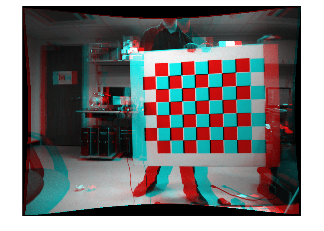
Rectify the images using 'full' output view.

[J1_full,J2_full] = rectifyStereoImages(I1,I2,stereoParams,OutputView='full');

Display the result for 'full' output view.

figure; 
imshow(stereoAnaglyph(J1_full,J2_full));
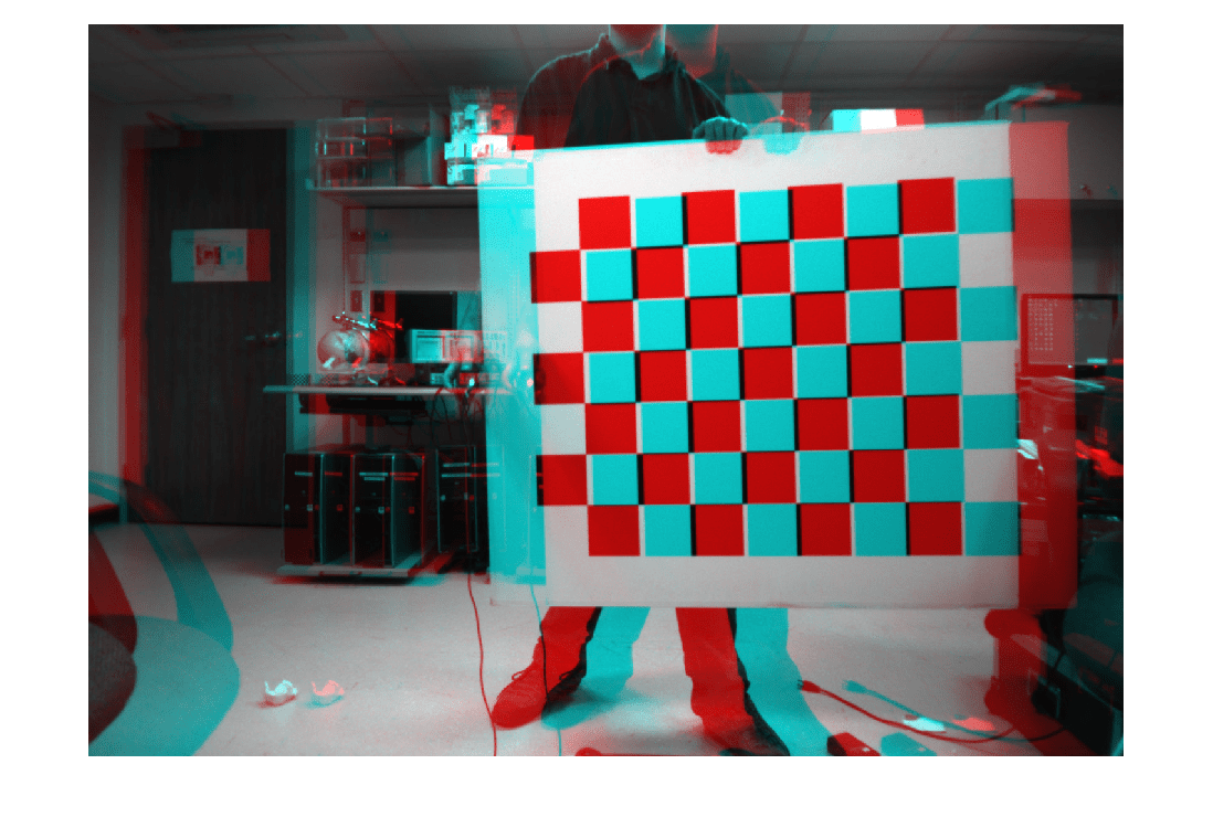
Figure contains an axes object. The axes object contains an object of type image.

Rectify the images using 'valid' output view. This is most suitable for computing disparity.

[J1_valid,J2_valid] = rectifyStereoImages(I1,I2,stereoParams,OutputView='valid');

Display the result for 'valid' output view.

figure; 
imshow(stereoAnaglyph(J1_valid,J2_valid));

Figure contains an axes object. The axes object contains an object of type image.

Input Arguments

collapse all

Input image corresponding to camera 1, specified as an M-by-N-by-3 truecolor image or an M-by-N 2-D grayscale array. Input images I1 and I2 must also be real, finite, and nonsparse. The input images must be the same class.

Data Types: uint8 | uint16 | int16 | single | double | logical

Input image corresponding to camera 2, specified as an M-by-N-by-3 truecolor image or an M-by-N 2-D grayscale array. Input images I1 and I2 must be real, finite, and nonsparse. The input images must also be the same class.

Data Types: uint8 | uint16 | int16 | single | double | logical

Stereo camera system parameters, specified as a stereoParameters object.

Data Types: uint8 | uint16 | int16 | single | double

Projective transformations for image 1, specified as a projtform2d object. You can get a projtform2d object using the estimateStereoRectification function.

Data Types: single | double

Projective transformations for image 2, specified as a projtform2d object. You can get a projtform2d object using the estimateStereoRectification function.

Data Types: single | double

Interpolation method, specified as either "linear", "nearest", or "cubic".

Name-Value Arguments

Specify optional pairs of arguments as Name1=Value1,...,NameN=ValueN, where Name is the argument name and Value is the corresponding value. Name-value arguments must appear after other arguments, but the order of the pairs does not matter.

Example: OutputView="valid" sets the OutputView argument to "valid".

Size of rectified images, specified as "full" or "valid". When you set this parameter to "full", the rectified images include all pixels from the original images. When you set this value to "valid", the output images are cropped to the size of the largest common rectangle containing valid pixels.

When there is no overlap between rectified images, set OutputView to "full".

Output pixel fill values, specified as numeric scalar or three-element numeric vector. When the corresponding inverse-transformed location in the input image is completely outside the input image boundaries, use the fill values for output pixels. If I1 and I2 are 2-D grayscale images, then you must set FillValues to a numeric scalar. If I1 and I2 are truecolor images, then you can set FillValues to a scalar or a three-element vector of RGB values.

Output Arguments

collapse all

Undistorted and rectified version of I1, returned as an M-by-N-by-3 truecolor image or as an M-by-N 2-D grayscale image.

Stereo image rectification projects images onto a common image plane in such a way that the corresponding points have the same row coordinates. This image projection makes the image appear as though the two cameras are parallel. Use the disparityBM or disparitySGM functions to compute a disparity map from the rectified images for 3-D scene reconstruction.

Undistorted and rectified version of I2, returned as an M-by-N-by-3 truecolor image or as an M-by-N 2-D grayscale image.

Stereo image rectification projects images onto a common image plane in such a way that the corresponding points have the same row coordinates. This image projection makes the image appear as though the two cameras are parallel. Use the disparityBM or disparitySGM functions to compute a disparity map from the rectified images for 3-D scene reconstruction.

Reprojection matrix, returned as a 4-by-4 matrix of the form:

[100cx010cy000f001/b0],

where f and [cx,cy] are the focal length and principal point of rectified camera 1, respectively. b is the baseline of the virtual rectified stereo camera.

Use the reconstructScene function with the reprojectionMatrix to reproject a 2-D point in a disparity map to a 3-D point in the rectified camera coordinate system of camera 1.

Rectified camera one projection matrix, returned as 3-by-4 matrix. Use camMatrix1 and camMatrix2 to project 3-D world points in camera one's coordinate system into the image plane of J1 and J2, respectively.

Use camMatrix1 to project 3-D world points in the rectified camera one coordinate system into the image plane of J1.

Data Types: single | double

Camera two rectified projection matrix, returned as 3-by-4 matrix. Use camMatrix1 and camMatrix2 to project 3-D world points in camera one's coordinate system into the image plane of J1 and J2, respectively.

Use camMatrix2 to project 3-D world points in the rectified camera two coordinate system into the image plane of J2.

Data Types: single | double

Camera one rotation matrix related to camera one rectified projection, returned as a 3-by-3 matrix. The R1 rotation matrix relate 3-D points from the unrectified camera one coordinate system to points in the rectified camera one coordinate system.

Data Types: single | double

Camera two rotation matrix related to camera one rectified projection, returned as a 3-by-3 matrix. The R2 rotation matrix relate 3-D points from the unrectified camera two coordinate system to points in the rectified camera two coordinate system.

Data Types: single | double

Tips

  • The Computer Vision Toolbox™ rectification algorithm requires that the epipole for each image lie outside of the image. If the epipole lies within the image, you can first transform the images into polar coordinates as described in the rectification method proposed by Marc Pollefeys, Reinhard Koch, and Luc Van Gool [2].

References

[1] G. Bradski and A. Kaehler, Learning OpenCV : Computer Vision with the OpenCV Library. Sebastopol, CA: O'Reilly, 2008.

Extended Capabilities

Version History

Introduced in R2014a

expand all