What Is Camera Calibration?
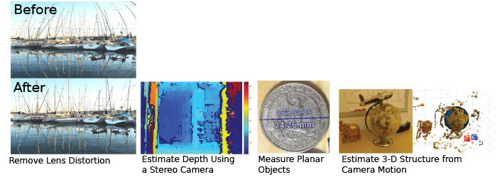
Geometric camera calibration, also referred to as camera resectioning, estimates the parameters of a lens and image sensor of an image or video camera. You can use these parameters to correct for lens distortion, measure the size of an object in world units, or determine the location of the camera in the scene. These tasks are used in applications such as machine vision to detect and measure objects. They are also used in robotics, for navigation systems, and 3-D scene reconstruction.
Examples of what you can do after calibrating your camera:
Camera parameters include intrinsics, extrinsics, and distortion coefficients. To estimate the camera parameters, you need to have 3-D world points and their corresponding 2-D image points. You can get these correspondences using multiple images of a calibration pattern, such as a checkerboard. Using the correspondences, you can solve for the camera parameters. After you calibrate a camera, to evaluate the accuracy of the estimated parameters, you can:
Plot the relative locations of the camera and the calibration pattern
Calculate the reprojection errors.
Calculate the parameter estimation errors.
Use the Camera Calibrator to perform camera calibration and evaluate the accuracy of the estimated parameters.
Camera Models
The Computer Vision Toolbox™ contains calibration algorithms for the pinhole camera model and the fisheye camera model. You can use the fisheye model with cameras up to a field of view (FOV) of 195 degrees.
The pinhole calibration algorithm is based on the model proposed by Jean-Yves Bouguet [3]. The model includes, the pinhole camera model [1] and lens distortion [2].The pinhole camera model does not account for lens distortion because an ideal pinhole camera does not have a lens. To accurately represent a real camera, the full camera model used by the algorithm includes the radial and tangential lens distortion.
Because of the extreme distortion a fisheye lens produces, the pinhole model cannot model a fisheye camera. For details on camera calibration using the fisheye model, see Fisheye Calibration Basics.
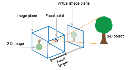
Pinhole Camera Model
A pinhole camera is a simple camera without a lens and with a single small aperture. Light rays pass through the aperture and project an inverted image on the opposite side of the camera. Think of the virtual image plane as being in front of the camera and containing the upright image of the scene.
The pinhole camera parameters are represented in a 3-by-4 matrix called the camera matrix. This matrix maps the 3-D world scene into the image plane. The calibration algorithm calculates the camera matrix using the extrinsic and intrinsic parameters. The extrinsic parameters represent the location of the camera in the 3-D scene. The intrinsic parameters represent the optical center and focal length of the camera.

The world points are transformed to camera coordinates using the extrinsic parameters. The camera coordinates are mapped into the image plane using the intrinsics parameters.
![World to camera to image, line of site showing that extrinsic vector [Rt] used for world to camera transformation, and intrinsics K is used for the camera to image transformation.](calibration-cameramodel-coords.png)
Camera Calibration Parameters
The calibration algorithm calculates the camera matrix using the extrinsic and intrinsic parameters. The extrinsic parameters represent a rigid transformation from 3-D world coordinate system to the 3-D camera’s coordinate system. The intrinsic parameters represent a projective transformation from the 3-D camera’s coordinates into the 2-D image coordinates.
Extrinsic Parameters
The extrinsic parameters consist of a rotation, R, and a translation, t. The origin of the camera’s coordinate system is at its optical center and its x- and y-axis define the image plane.
Intrinsic Parameters
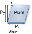
The intrinsic parameters include the focal length, the optical center, also known as the principal point, and the skew coefficient. The camera intrinsic matrix, K, is defined as:
The pixel skew is defined as:
| — Optical center (the principal point), in pixels. |
| — Focal length in pixels. — Focal length in world units, typically expressed in millimeters. — Size of the pixel in world units. |
| — Skew coefficient, which is non-zero if the image
axes are not perpendicular. |
Distortion in Camera Calibration
The camera matrix does not account for lens distortion because an ideal pinhole camera does not have a lens. To accurately represent a real camera, the camera model includes the radial and tangential lens distortion.
Some camera calibration models use up to 15 distortion coefficients to model more complex lens distortions. The camera model described on this page uses 5 distortion coefficients. Most camera lenses can be modeled using 5 distortion coefficients. For fisheye lenses, use the Scaramuzza model Intrinsic Parameters.
Radial Distortion
Radial distortion occurs when light rays bend more near the edges of a lens than they do at its optical center. The smaller the lens, the greater the distortion.

The radial distortion coefficients model this type of distortion. The distorted points are denoted as (xdistorted, ydistorted):
xdistorted = x(1 + k1*r2 + k2*r4 + k3*r6)
ydistorted= y(1 + k1*r2 + k2*r4 + k3*r6)
x, y — Undistorted pixel locations. x and y are in normalized image coordinates. Normalized image coordinates are calculated from pixel coordinates by translating to the optical center and dividing by the focal length in pixels. Thus, x and y are dimensionless.
k1, k2, and k3 — Radial distortion coefficients of the lens.
r2 = x2 + y2
Typically, two coefficients are sufficient for calibration. For severe distortion, such as in wide-angle lenses, you can select three coefficients to include k3.
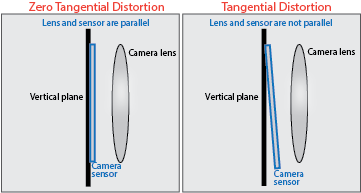
Tangential Distortion
Tangential distortion occurs when the lens and the image plane are not parallel. The tangential distortion coefficients model this type of distortion.
The distorted points are denoted as (xdistorted, ydistorted):
xdistorted = x + [2 * p1 * x * y + p2 * (r2 + 2 * x2)]
ydistorted = y + [p1 * (r2 + 2 *y2) + 2 * p2 * x * y]
x, y — Undistorted pixel locations. x and y are in normalized image coordinates. Normalized image coordinates are calculated from pixel coordinates by translating to the optical center and dividing by the focal length in pixels. Thus, x and y are dimensionless.
p1 and p2 — Tangential distortion coefficients of the lens.
r2 = x2 + y2
References
[1] Zhang, Z. “A Flexible New Technique for Camera Calibration.” IEEE Transactions on Pattern Analysis and Machine Intelligence. Vol. 22, No. 11, 2000, pp. 1330–1334.
[2] Heikkila, J., and O. Silven. “A Four-step Camera Calibration Procedure with Implicit Image Correction.” IEEE International Conference on Computer Vision and Pattern Recognition.1997.
[3] Bouguet, J. Y. “Camera Calibration Toolbox for Matlab.” Computational Vision at the California Institute of Technology.
[4] Bradski, G., and A. Kaehler. Learning OpenCV: Computer Vision with the OpenCV Library. Sebastopol, CA: O'Reilly, 2008.
See Also
Apps
Topics
- Implement Visual SLAM in MATLAB
- Using the Single Camera Calibrator App
- Using the Stereo Camera Calibrator App
- Evaluating the Accuracy of Single Camera Calibration
- Fisheye Calibration Basics
- Configure Monocular Fisheye Camera (Automated Driving Toolbox)
- Calibrate a Monocular Camera (Automated Driving Toolbox)
- Measuring Planar Objects with a Calibrated Camera
- Structure from Motion from Two Views
- Structure from Motion from Multiple Views