802.11ac Waveform Generation with MAC Frames
This example shows how to generate an IEEE® 802.11ac™ (Wi-Fi 5) transmission containing MAC frames suitable for performing radio packet error rate (PER) receiver tests.
Introduction
WLAN Toolbox™ can be used to generate standard compliant waveforms for performing receiver tests. A basic WLAN receiver test scenario is shown in the diagram below.
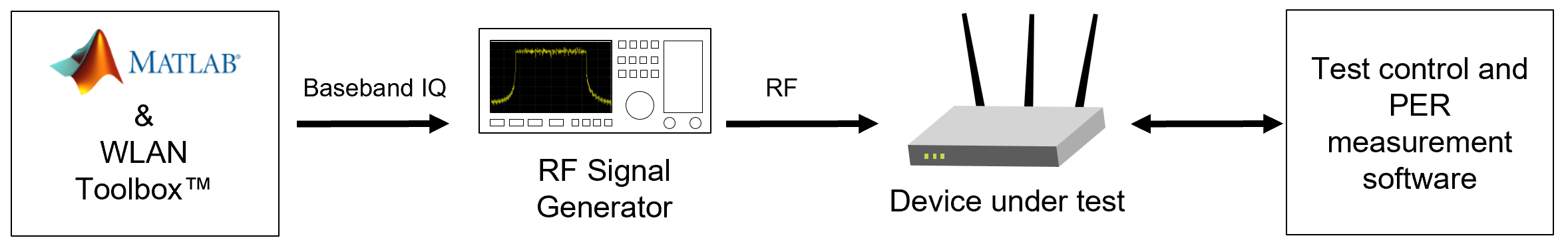
The device under test (DUT) is stimulated with RF test vectors, usually through a wired link. The packet error rate (PER) is a metric used to test the performance of a receiver at a given receive signal power in the presence of noise, interference, or other impairments. The PER is defined as the number of incorrectly decoded packets divided by the total number of transmitted packets.
The frame check sequence (FCS) within a MAC frame is used to determine whether a MAC frame has been decoded correctly by the receiver, and therefore whether the packet has been received in error. The general MAC frame for IEEE 802.11ac contains the following fields:
MAC header
Frame body
FCS
The data to transmit from a higher layer is contained within the frame body of the MAC frame. The transmitter uses a cyclic redundancy check over the MAC header and frame body field to generate the FCS value. The receiver calculates the CRC and compares this to the received FCS field to determine if an error has occurred during transmission.
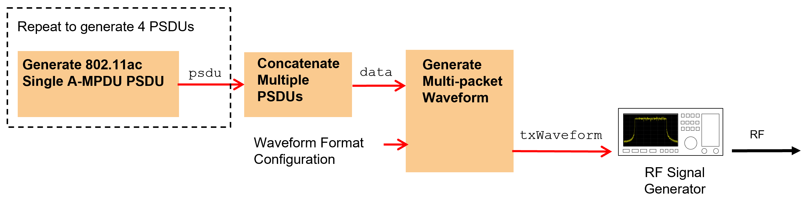
In this example an IEEE 802.11ac waveform consisting of multiple VHT format packets is generated. The wlanWaveformGenerator function can be used to generate a waveform containing one or more packets. The wlanWaveformGenerator function consumes physical layer service data units (PSDUs) for each packet and performs the appropriate physical layer processing to create the waveform. A PSDU containing a MAC header and valid FCS can be generated using the wlanMACFrame function. In this example a multi-packet baseband waveform containing MAC packets is synthesized. This waveform may be downloaded to a signal generator for RF transmission and used for receiver PER testing. Source code is provided to download and play the waveform using a Keysight Technologies™ N5172B signal generator. The example processing is illustrated in the following diagram:
802.11ac VHT Format Configuration
The format-specific configuration of a VHT waveform synthesized with the wlanWaveformGenerator function is described by the VHT format configuration object, wlanVHTConfig. The properties of the object contain the configuration. In this example an object is configured for a 160 MHz bandwidth, 1 transmit antenna, 1 space-time stream and QPSK rate 1/2 (MCS 1).
vhtCfg = wlanVHTConfig;             % Create packet configuration
vhtCfg.ChannelBandwidth = 'CBW160'; % 160 MHz channel bandwidth
vhtCfg.NumTransmitAntennas = 1;     % 1 transmit antenna
vhtCfg.NumSpaceTimeStreams = 1;     % 1 space-time stream
vhtCfg.MCS = 1;                     % Modulation: QPSK Rate: 1/2
Waveform Generation Configuration
The wlanWaveformGenerator function can be configured to generate one or more packets and add an idle time between each packet. The function can be configured to generate an oversampled or nominal rate waveform. In this example four oversampled packets with a 20 microsecond idle period will be created.
numPackets = 4;   % Generate 4 packets
idleTime = 20e-6; % 20 microseconds idle period after packet
oversamplingFactor = 1.5; % Oversample waveform 1.5x nominal baseband rate
The PSDU transmitted in each packet is scrambled using a random seed for each packet. This is accomplished by specifying a vector of scrambler initialization seeds. The valid range of the seed is between 1 and 127 inclusive.
% Initialize the scrambler with a random integer for each packet
scramblerInitialization = randi([1 127],numPackets,1);
Create a PSDU for Each Packet
For an IEEE 802.11ac data transmission the MAC frame is termed a MAC protocol data unit (MPDU), the MAC header is termed the MPDU header, and the frame body is an aggregated MAC service data unit (A-MSDU). One or more MPDUs are delimited, padded and aggregated to create an aggregated MPDU (A-MPDU). The A-MPDU is delimited and padded to form the physical layer service data unit (PSDU) which is coded and modulated to create the transmitted packet. This process of encapsulation is shown in the following diagram:
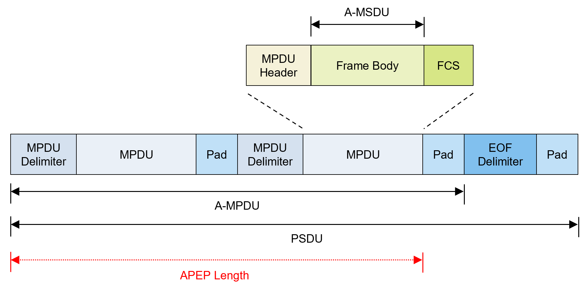
In this example a PSDU is created containing a single MPDU for each packet. The MPDU consists of an MPDU header, A-MSDU frame containing concatenated A-MSDU subframes with random data and valid FCS. The wlanMACFrame function creates an A-MPDU with EOF delimiters and padding, i.e. the PSDU, as specified in [ 1 ]. It also returns the length of the A-MPDU, termed as the APEP Length, which is used to set the APEPLength property of the VHT configuration object. A PSDU is generated for each packet and is concatenated into a vector data for transmission with the wlanWaveformGenerator function. The processing to create the concatenated PSDU bits data is shown in the diagram below:

% Create frame configuration
macCfg = wlanMACFrameConfig('FrameType', 'QoS Data');
macCfg.FrameFormat = 'VHT';     % Frame format
macCfg.MSDUAggregation = true;  % Form A-MSDUs internally
bitsPerByte = 8;                % Number of bits in 1 byte
data = [];

for i=1:numPackets
    % Get MSDU lengths to create a random payload for forming an A-MPDU of
    % 4048 octets (pre-EOF padding)
    msduLengths = wlanMSDULengths(4048, macCfg, vhtCfg);
    msdu = cell(numel(msduLengths), 1);

    % Create MSDUs with the obtained lengths
    for j = 1:numel(msduLengths)
        msdu{j} = randi([0 255], 1, msduLengths(j));
    end

    % Generate PSDU bits containing A-MPDU with EOF delimiters and padding
    [psdu, apepLength] = wlanMACFrame(msdu, macCfg, vhtCfg, 'OutputFormat', 'bits');

    % Set the APEP length in the VHT configuration
    vhtCfg.APEPLength = apepLength;

    % Concatenate packet PSDUs for waveform generation
    data = [data; psdu]; %#ok<AGROW>
end
Generate a Baseband Waveform
The concatenated PSDU bits for all packets, data, are passed as an argument to the wlanWaveformGenerator function along with the VHT packet configuration object vhtCfg. This configures the waveform generator to synthesize an 802.11ac VHT waveform. To generate 802.11n™ HT or other format waveforms, use a different format configuration object, for example wlanHTConfig or wlanNonHTConfig. The waveform generator is additionally configured using name-value pairs to generate multiple oversampled packets with a specified idle time between packets, and initial scrambler states.
% Generate baseband VHT packets
txWaveform = wlanWaveformGenerator(data,vhtCfg, ...
    'NumPackets',numPackets,'IdleTime',idleTime, ...
    'ScramblerInitialization',scramblerInitialization, ...
    'OversamplingFactor',oversamplingFactor);

fs = wlanSampleRate(vhtCfg,'OversamplingFactor',oversamplingFactor);
disp(['Baseband sampling rate: ' num2str(fs/1e6) ' Msps']);
Baseband sampling rate: 240 Msps
The magnitude of the baseband waveform is displayed below. Note the number of packets and idle time configured.
figure;
plot(abs(txWaveform));
xlabel('Sample index');
ylabel('Magnitude');
title('Baseband IEEE 802.11ac Waveform');
legend('Transmit antenna 1');

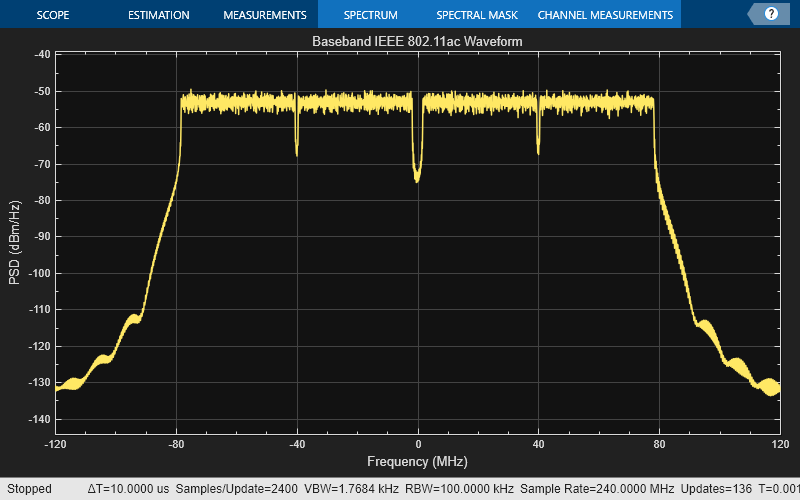
View the frequency spectrum of the generated time domain waveform by using the DSP System Toolbox spectrumAnalyzer. As expected, the 160 MHz signal bandwidth is clearly visible.
spectrumScope = spectrumAnalyzer;
spectrumScope.SampleRate = fs;
spectrumScope.SpectrumType = 'power-density';
spectrumScope.RBWSource = 'property';
spectrumScope.RBW = 100e3;
spectrumScope.AveragingMethod = 'exponential';
spectrumAnalyze.ForgettingFactor = 0.99;
spectrumScope.YLabel = 'PSD';
spectrumScope.Title = 'Baseband IEEE 802.11ac Waveform';
spectrumScope(txWaveform);
release(spectrumScope)
Generate Over-the-Air Signal Using an RF Signal Generator
The baseband waveform created by WLAN Toolbox can now be downloaded to a signal generator to perform receiver tests. Use Instrument Control Toolbox to generate an RF signal with a center frequency of 5.25 GHz RF using the Keysight Technologies N5172B signal generator.
% Control whether to download the waveform to the waveform generator
playOverTheAir = false;

% Download the baseband IQ waveform to the instrument. Generate the RF
% signal at a center frequency of 5.25 GHz and output power of -10 dBm.
if playOverTheAir
    fc = 5.25e9; %#ok<UNRCH> % Center frequency
    power = -10;     % Output power
    loopCount = Inf; % Number time to loop

    % Configure the signal generator, download the waveform and loop
    rf = rfsiggen();
    rf.Resource = 'TCPIP0::192.168.0.1::inst0::INSTR';
    rf.Driver = 'AgRfSigGen';
    connect(rf);                  % Connect to the instrument
    download(rf,txWaveform.',fs); % Download the waveform to the instrument
    start(rf,fc,power,loopCount); % Start transmitting waveform

    % When you have finished transmitting, stop the waveform output
    stop(rf);
    disconnect(rf);
end
Selected Bibliography
IEEE Std 802.11™-2020 IEEE Standard for Information technology - Telecommunications and information exchange between systems - Local and metropolitan area networks - Specific requirements - Part 11: Wireless LAN Medium Access Control (MAC) and Physical Layer (PHY) Specifications.