Main Content

wlanWaveformGenerator

Generate WLAN waveform

Description

example

waveform = wlanWaveformGenerator(bits,cfg) generates a waveform for bits, the specified information bits, and cfg, the physical layer (PHY) format configuration. For more information, see IEEE 802.11 PPDU Format.

example

waveform = wlanWaveformGenerator(bits,cfg,Name,Value) specifies additional options using one or more name-value pair arguments.

Examples

collapse all

Configure and generate a WLAN waveform containing an EHT TB packet.

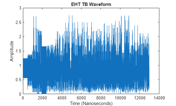
Create a configuration object for a WLAN EHT TB transmission.

cfgEHTTB = wlanEHTTBConfig;

Get the PSDU length, in bytes, from the configuration object by using the psduLength object function.

length = psduLength(cfgEHTTB);

Generate a PSDU of the relevant length, converting bytes to bits by multiplying by eight.

psdu = randi([0 1],8*length,1);

Generate and plot the waveform.

waveform = wlanWaveformGenerator(psdu,cfgEHTTB);
plot(abs(waveform));
title("EHT TB Waveform");
xlabel("Time (Nanoseconds)");
ylabel("Amplitude");

Figure contains an axes object. The axes object with title EHT TB Waveform, xlabel Time (Nanoseconds), ylabel Amplitude contains an object of type line.

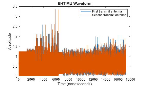
Create a configuration object for a non-OFDMA EHT MU packet. Set the channel bandwidth to 160 MHz.

cfgEHTMU = wlanEHTMUConfig("CBW160");

Obtain the PSDU length, in bytes, from the configuration object by using the psduLength object function.

length = psduLength(cfgEHTMU);

Generate a PSDU of the relevant length.

psdu = randi([0 1],8*length,1);

Generate and plot the waveform.

waveform = wlanWaveformGenerator(psdu,cfgEHTMU);
figure;
plot(abs(waveform));
title('EHT MU Waveform');
xlabel('Time (nanoseconds)');
ylabel('Amplitude');

Figure contains an axes object. The axes object with title EHT MU Waveform, xlabel Time (nanoseconds), ylabel Amplitude contains an object of type line.

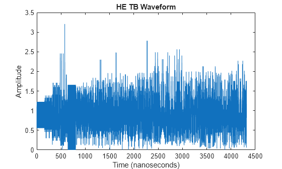
Configure and generate a WLAN waveform containing an HE TB uplink packet.

Create a configuration object for a WLAN HE TB uplink transmission.

cfgHETB = wlanHETBConfig;

Obtain the PSDU length, in bytes, from the configuration object by using the getPSDULength object function.

psduLength = getPSDULength(cfgHETB);

Generate a PSDU of the relevant length.

psdu = randi([0 1],8*psduLength,1);

Generate and plot the waveform.

waveform = wlanWaveformGenerator(psdu,cfgHETB);
figure;
plot(abs(waveform));
title('HE TB Waveform');
xlabel('Time (nanoseconds)');
ylabel('Amplitude');

Figure contains an axes object. The axes object with title HE TB Waveform, xlabel Time (nanoseconds), ylabel Amplitude contains an object of type line.

Generate a time-domain signal for an 802.11ac VHT transmission with one packet.

Create a VHT configuration object. Assign two transmit antennas and two spatial streams, and disable space-time block coding (STBC). Set the modulation and coding scheme to 1, which assigns QPSK modulation and a 1/2 rate coding scheme per the 802.11 standard. Set the number of bytes in the A-MPDU pre-EOF padding, APEPLength, to 1024.

cfg = wlanVHTConfig('NumTransmitAntennas',2,'NumSpaceTimeStreams',2,'STBC',0,'MCS',1,'APEPLength',1024);

Generate the transmit waveform.

bits = [1;0;0;1];
txWaveform = wlanWaveformGenerator(bits,cfg);

HE MU-MIMO Configuration With SIGB Compression

Generate a full bandwidth HE MU-MIMO configuration at 20 MHz bandwidth with SIGB compression. All three users are on a single content channel, which includes only the user field bits.

cfgHE = wlanHEMUConfig(194);
cfgHE.NumTransmitAntennas = 3;

Create PSDU data for all users.

psdu = cell(1,numel(cfgHE.User));
psduLength = getPSDULength(cfgHE);
for j = 1:numel(cfgHE.User)
    psdu = randi([0 1],psduLength(j)*8,1,'int8');
end

Generate and plot the waveform.

y = wlanWaveformGenerator(psdu,cfgHE);
plot(abs(y))

Figure contains an axes object. The axes object contains 3 objects of type line.

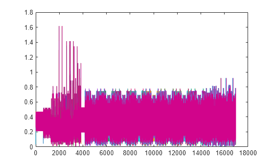
Generate a full bandwidth HE MU-MIMO waveform at 80 MHz bandwidth with SIGB compression. HE-SIG-B content channel 1 has four users. HE-SIG-B content channel 2 has three users.

cfgHE = wlanHEMUConfig(214);
cfgHE.NumTransmitAntennas = 7;

Create PSDU data for all users.

psdu = cell(1,numel(cfgHE.User));
psduLength = getPSDULength(cfgHE);
for j = 1:numel(cfgHE.User)
    psdu = randi([0 1],psduLength(j)*8,1,'int8');
end

Generate and plot the waveform.

y = wlanWaveformGenerator(psdu,cfgHE);
plot(abs(y));

Figure contains an axes object. The axes object contains 7 objects of type line.

HE MU-MIMO Configuration Without SIGB Compression

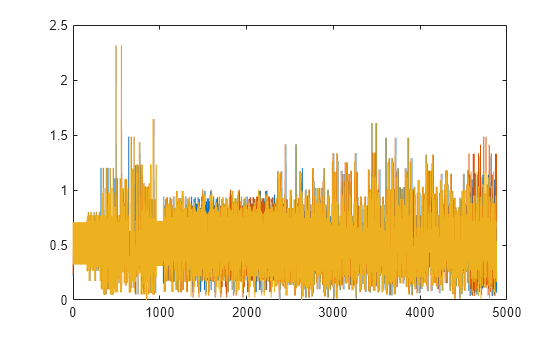
Generate a full bandwidth HE MU-MIMO configuration at 20 MHz bandwidth without SIGB compression. All three users are on a single content channel, which includes both common and user field bits.

cfgHE = wlanHEMUConfig(194);
cfgHE.SIGBCompression = false;
cfgHE.NumTransmitAntennas = 3;

Create PSDU data for all users.

psdu = cell(1,numel(cfgHE.User));
psduLength = getPSDULength(cfgHE);
for j = 1:numel(cfgHE.User)
    psdu = randi([0 1],psduLength(j)*8,1,'int8');
end

Generate and plot the waveform.

y = wlanWaveformGenerator(psdu,cfgHE);
plot(abs(y))

Figure contains an axes object. The axes object contains 3 objects of type line.

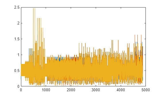
Generate an 80 MHz HE MU waveform for six users without SIGB compression. HE-SIG-B content channel 1 has four users. HE-SIG-B content channel 2 has two users.

cfgHE = wlanHEMUConfig([202 114 192 193]);
cfgHE.NumTransmitAntennas = 6;
for i = 1:numel(cfgHE.RU)
    cfgHE.RU{i}.SpatialMapping = 'Fourier';
end

Create PSDU data for all users.

psdu = cell(1,numel(cfgHE.User));
psduLength = getPSDULength(cfgHE);
for j = 1:numel(cfgHE.User)
    psdu = randi([0 1],psduLength(j)*8,1,'int8');
end

Generate and plot the waveform.

y = wlanWaveformGenerator(psdu,cfgHE);
plot(abs(y));

Figure contains an axes object. The axes object contains 6 objects of type line.

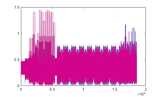
Generate a full bandwidth HE MU-MIMO waveform at 80 MHz bandwidth without SIGB compression. HE-SIG-B content channel 1 has seven users. HE-SIG-B content channel 2 has zero users.

cfgHE = wlanHEMUConfig([214 115 115 115]);
cfgHE.NumTransmitAntennas = 7;

Create PSDU data for all users.

psdu = cell(1,numel(cfgHE.User));
psduLength = getPSDULength(cfgHE);
for j = 1:numel(cfgHE.User)
    psdu = randi([0 1],psduLength(j)*8,1,'int8');
end

Generate and plot the waveform.

y = wlanWaveformGenerator(psdu,cfgHE);
plot(abs(y))

Figure contains an axes object. The axes object contains 7 objects of type line.

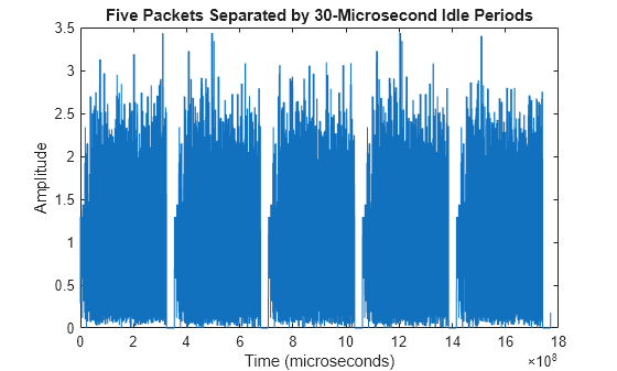
Generate a time-domain signal for an 802.11ac VHT transmission with five packets and a 30-microsecond idle period between packets. Use a random scrambler initial state for each packet.

Create a VHT configuration object and confirm the channel bandwidth for scaling the x-axis of the plot.

cfg = wlanVHTConfig;
disp(cfg.ChannelBandwidth)
CBW80

Generate and plot the waveform. Display the time in microseconds on the x-axis.

numPkts = 5;
bits = [1;0;0;1];
scramInit = randi([1 127],numPkts,1);
txWaveform = wlanWaveformGenerator(bits,cfg,'NumPackets',numPkts,'IdleTime',30e-6,'ScramblerInitialization',scramInit);
time = [0:length(txWaveform)-1]/80e-6;
plot(time,abs(txWaveform));
title('Five Packets Separated by 30-Microsecond Idle Periods');
xlabel ('Time (microseconds)');
ylabel('Amplitude');

Figure contains an axes object. The axes object with title Five Packets Separated by 30-Microsecond Idle Periods, xlabel Time (microseconds), ylabel Amplitude contains an object of type line.

Input Arguments

collapse all

Information bits for a single user, including any MAC padding representing multiple concatenated PSDUs, specified as one of these values.

  • 0 or 1.

  • A binary-valued vector.

  • A one-by-one cell containing a binary-valued scalar or vector– The specified bits apply to all users.

  • A vector cell array of binary-valued scalars or vectors – Each element applies to each user correspondingly. The length of this cell array must be equal to the number of users. For each user, if the number of bits required across all packets of the generation exceeds the length of the vector provided, the function loops the applied bit vector. Looping on the bits allows you to define a short pattern, for example, [1; 0; 0; 1], that is repeated as the input to the PSDU coding across packets and users. In each packet generation, for the kth user, the kth element of the PSDULength property of the cfg input indicates the number of data bytes taken from its stream. To compute the number of bits, multiply PSDULength by 8.

Internally, the function loops this input to generate the specified number of packets. The PSDULength property of the cfg input specifies the number of data bits taken from the bit stream for each transmission packet generated. The 'NumPackets' input specifies the number of packets to generate.

Example: [1 1 0 1 0 1 1]

Data Types: double | int8

Packet format configuration, specified as one of these objects: wlanHEMUConfig, wlanHESUConfig, wlanHETBConfig, wlanEHTMUConfig, wlanEHTTBConfig, wlanWURConfig, wlanDMGConfig, wlanS1GConfig, wlanVHTConfig, wlanHTConfig, or wlanNonHTConfig. The type of object you specify determines the IEEE® 802.11™ format of the generated waveform.

The properties of the packet format configuration object determine the data rate and PSDU length of generated PPDUs.

Name-Value Arguments

Specify optional pairs of arguments as Name1=Value1,...,NameN=ValueN, where Name is the argument name and Value is the corresponding value. Name-value arguments must appear after other arguments, but the order of the pairs does not matter.

Before R2021a, use commas to separate each name and value, and enclose Name in quotes.

Example: 'NumPackets',21,'ScramblerInitialization',[52,17]

Number of packets to generate in a single function call, specified as a positive integer.

Data Types: double

Idle time, in seconds, added after each packet, specified as a nonnegative scalar. Except for the default value, this input must be greater than or equal to:

  • 1e-6 for DMG format

  • 2e-6 for all other formats

Example: 2e-5

Data Types: double

Oversampling factor, specified as a scalar greater than or equal to 1. The oversampled cyclic prefix length must be an integer number of samples. For more information about oversampling, see FFT-Based Oversampling.

Dependencies

This argument applies only for EHT, HE, WUR, VHT, HT, S1G, and non-HT OFDM formats.

Data Types: single | double | int8 | int16 | int32 | int64 | uint8 | uint16 | uint32 | uint64

Initial scrambler state or initial pseudorandom scrambler sequence for each generated packet and each user, specified as one of these values.

  • An integer in the interval [1, 127] — This input represents the initial scrambler state for all packets and users in HE, S1G, VHT, and HT waveforms, and non-HT OFDM waveforms with bandwidth signaling disabled. For multi-user and multipacket waveforms, the function uses the value you specify for all packets and users. The default value, 93, is the example state in Section I.1.5.2 of [1]. For more information, see Scrambler Initialization.

  • An integer in the interval [1, 2047]. This input represents the initial scrambler state for all packets and users in EHT waveforms. For multi-user and multipacket waveforms, the function uses the value you specify for all packets and users.

  • An integer in the interval [min, max] — This input represents the initial pseudorandom scrambler sequence of a non-HT transmission with bandwidth signaling enabled, described in Table 17-7 of [1]. If you do not specify this input, the function uses the NB most significant bits of the default value, 93. The values of min, max, and NB depend on the values of the BandwidthOperation and ChannelBandwidth properties of the cfg input according to this table.

    Value of cfg.BandwidthOperationValue of cfg.ChannelBandwidthValue of minValue of maxValue of NB
    'Absent''CBW20'1315
    'Absent''CBW5', 'CBW10', 'CBW40', 'CBW80', or 'CBW160'0315
    'Static' or 'Dynamic''CBW20'1154
    'Static' or 'Dynamic''CBW5', 'CBW10', 'CBW40', 'CBW80', or 'CBW160'0154

  • A matrix of integers in the interval [1, 127], of size NP-by-NUsers — Each element represents an initial state of the scrambler for each packet and for each user in VHT, S1G, and HE multi-user (MU) waveforms comprising multiple packets. Each column specifies the initial states for a single user. You can specify up to eight columns for HE MU waveforms, or up to four columns for VHT and S1G. If you specify a single column, the function uses the same initial states for all users. Each row represents the initial state of each packet to generate. A matrix with multiple rows enables you to use a different initial state per packet, where the first row contains the initial state of the first packet. If the number of packets to generate exceeds the number of rows of the matrix provided, the function loops the rows internally.

    • NP is the number of packets.

    • NUsers is the number of users.

  • A matrix of integers in the interval [1, 2047], of size NP-by-NUsers — Each element represents an initial state of the scrambler for each packet and for each user in EHT multi-user (MU) waveforms comprising multiple packets. Each column specifies the initial states for a single user. You can specify up to 144 columns for EHT MU waveforms. If you specify a single column, the function uses the same initial states for all users. Each row represents the initial state of each packet to generate. A matrix with multiple rows enables you to use a different initial state per packet, where the first row contains the initial state of the first packet. If the number of packets to generate exceeds the number of rows of the matrix provided, the function loops the rows internally.

    • NP is the number of packets.

    • NUsers is the number of users.

For DMG transmissions, specifying this argument overrides the value of the ScramblerInitialization property of the wlanDMGConfig configuration object.

Example: [3 56 120]

Dependencies

This argument is not valid for WUR and DSSS non-HT formats.

Data Types: double | int8

Duration, in seconds, of the window transition applied to each OFDM symbol, specified as a nonnegative scalar. The function does not apply windowing if you specify this input as 0. This table shows the default and maximum values permitted for each format, the type of guard interval, and the channel bandwidth.

FormatBandwidthPermitted WindowTransitionTime (seconds)
Default ValueMaximum ValueMaximum Permitted Value Based on Guard Interval Duration
3.2 µs1.6 µs

0.8 µs

(Long)

0.4 µs

(Short)

EHT MU and EHT TB

20, 40, 80, 160, or 320 MHz

1.0e-07

Not applicable

6.4e-06

3.2e-06

1.6e-06

Not applicable

HE SU, HE MU, and HE TB

20, 40, 80, or 160 MHz

1.0e-07

Not applicable

6.4e-06

3.2e-06

1.6e-06

Not applicable

VHT

20, 40, 80, or 160 MHz

1.0e-07

Not applicable

Not applicable

Not applicable

1.6e-06

8.0e-07

HT-mixed

20 or 40 MHz

1.0e-07

Not applicable

Not applicable

Not applicable

1.6e-06

8.0e-07

non-HT

20, 40, 80, or 160 MHz

1.0e-07

Not applicable

Not applicable

Not applicable

1.6e-06

Not applicable

10 MHz

1.0e-07

Not applicable

Not applicable

Not applicable

3.2e-06

Not applicable

5 MHz

1.0e-07

Not applicable

Not applicable

Not applicable

6.4e-06

Not applicable

WUR20, 40, 80 MHz

1.0e-07

Not applicable

Not applicable

Not applicable

Not applicable

Not applicable

DMG

2640 MHz

6.0606e-09

(= 16/2640e6)

9.6969e-08

(= 256/2640e6)

Not applicable

Not applicable

Not applicable

Not applicable

S1G

1, 2, 4, 8, or 16 MHz

1.0e-07

Not applicable

Not applicable

Not applicable

1.6e-05

8.0e-06

Data Types: double

Output Arguments

collapse all

Packetized waveform, returned as an NS-by-NT matrix. NS is the number of time-domain samples, and NT is the number of transmit antennas. waveform contains one or more packets of the same PPDU format. Each packet can contain different information bits. Enable waveform packet windowing by setting the WindowTransitionTime input to a positive value. Windowing is enabled by default.

For more information, see Waveform Sampling Rate, OFDM Symbol Windowing, and Waveform Looping.

Data Types: double
Complex Number Support: Yes

More About

collapse all

IEEE 802.11 PPDU Format

Supported IEEE 802.11 PPDU formats defined for transmission include EHT, HE, WUR, VHT, HT, non-HT, S1G, and DMG. For all formats, the PPDU field structure includes preamble and data portions. For a detailed description of the packet structures for the various formats supported, see WLAN PPDU Structure.

Waveform Sampling Rate

At the output of this function, the generated waveform has a sampling rate equal to the channel bandwidth.

For all EHT, HE, VHT, HT, and non-HT format OFDM modulation, the channel bandwidth is configured via the ChannelBandwidth property of the format configuration object.

For the DMG format modulation schemes, the channel bandwidth is always 2640 MHz and the channel spacing is always 2160 MHz, as specified in sections 20.3.4 and E.1 of [1], respectively.

For the non-HT format DSSS modulation scheme, the chipping rate is always 11 MHz, as specified in section 16.1.1 of [1].

This table indicates the waveform sampling rates associated with standard channel spacing for each configuration format prior to filtering.

Configuration Object

Modulation Type

ChannelBandwidth Property Value

Channel Spacing (MHz)

Sampling Rate (MHz)

(FS, FC)

wlanEHTMUConfig and wlanEHTTBConfig

OFDMA

'CBW20'

20

FS = 20

'CBW40'

40

FS = 40

'CBW80'

80

FS = 80

'CBW160'

160

FS = 160

'CBW320'

320

FS = 320

wlanHEMUConfig, wlanHESUConfig, and wlanHETBConfig

OFDMA

'CBW20'

20

FS = 20

'CBW40'

40

FS = 40

'CBW80'

80

FS = 80

'CBW160'

160

FS = 160

wlanVHTConfig

OFDM

'CBW20'

20

FS = 20

'CBW40'

40

FS = 40

'CBW80'

80

FS = 80

'CBW160'

160

FS = 160

wlanHTConfig

OFDM

'CBW20'

20

FS = 20

'CBW40'

40

FS = 40

wlanNonHTConfig

DSSS/CCK

Not applicable

11

FC = 11

OFDM

'CBW5'

5

FS = 5

'CBW10'

10

FS = 10

'CBW20'

20

FS = 20

'CBW40'40FS = 40
'CBW80'80FS = 80
'CBW160160FS = 160
wlanWURConfigOFDM'CBW20'20

FS = 20

'CBW40'40

FS = 40

'CBW80'80

FS = 80

wlanDMGConfig

Control PHY

For DMG, the channel bandwidth is fixed at 2640 MHz.

2160

FC = ⅔ FS = 1760

SC

OFDM

FS = 2640

wlanS1GConfig

OFDM

'CBW1'

1

FS = 1

'CBW2'

2

FS = 2

'CBW4'

4

FS = 4

'CBW8'

8

FS = 8

'CBW16'

16

FS = 16

FS is the OFDM sampling rate.

FC is the chip rate for single-carrier, control PHY, DSSS, and CCK modulations.

OFDM Symbol Windowing

OFDM naturally lends itself to processing with Fourier transforms. A negative side effect of using an IFFT to process OFDM symbols is the resulting symbol-edge discontinuities. These discontinuities cause out-of-band emissions in the transition region between consecutive OFDM symbols. To smooth the discontinuity between symbols and reduce the intersymbol out-of-band emissions, you can use the wlanWaveformGenerator function to apply OFDM symbol windowing. To apply windowing, set the WindowTransitionTime input to a positive value.

When windowing is applied, the function adds transition regions to the leading and trailing edge of the OFDM symbol. Windowing extends the length of the OFDM symbol by WindowTransitionTime (TTR).

OFDM symbol and extended OFDM symbol with windowing

The extended waveform is windowed by pointwise multiplication in the time domain, using this windowing function specified in section 17.3.2.5 of [1]:

wT(t)={sin2[π2(12+tTTR)]if t[TTR2,TTR2],1if t[TTR2,TTTR2],sin2[π2(12+tTTR)]if t[TTTR2,T+TTR2].

The windowing function applies over the leading and trailing portion of the OFDM symbol:

  • TTR/2 to TTR/2

  • T – TTR/2 to T + TTR/2

Windowed OFDM symbol showing leading and trailing portion

After windowing is applied to each symbol, pointwise addition is used to combine the overlapped regions between consecutive OFDM symbols. Specifically, the trailing shoulder samples at the end of OFDM symbol 1 (T – TTR/2 to T + TTR/2) are added to the leading shoulder samples at the beginning of OFDM symbol 2 (–TTR/2 to TTR/2).

Combining overlapped regions of the consecutive windowed OFDM symbols

Smoothing the overlap between consecutive OFDM symbols in this manner reduces the out-of-band emissions. The function applies OFDM symbol windowing between:

  • Each OFDM symbol within a packet

  • Consecutive packets within the waveform, considering the idle time IdleTime between packets specified by the 'IdleTime' input

  • The last and the first packet of the generated waveform

Windowing DMG Format Packets

For the DMG format, windowing applies only to packets transmitted using the OFDM PHY and is applied only to the OFDM modulated symbols. For OFDM PHY, only the header and data symbols are OFDM modulated. The preamble (STF and CEF) and the training fields are single carrier modulated and are not windowed. Similar to the out-of-band emissions experienced by consecutive OFDM symbols, as shown here, the CEF and the first training subfield are subject to a nominal amount of out-of-band emissions from the adjacent windowed OFDM symbol.

Structure of DMG-OFDM PHY packet showing windowed and non-windowed OFDM symbols

For more information on how the function handles windowing for the consecutive packet idle time and for the last waveform packet, see Waveform Looping.

Waveform Looping

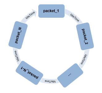
To produce a continuous input stream, you can have your code loop on a waveform from the last packet back to the first packet.

A circular flowchart showing waveform looping from the last packet back to the first packet

Applying windowing to the last and first OFDM symbols of the generated waveform smooths the transition between the last and first packet of the waveform. When the 'WindowTransitionTime' input is positive, the wlanWaveformGenerator function applies OFDM symbol windowing.

When looping a waveform, the last symbol of packet_N is followed by the first OFDM symbol of packet_1. If the waveform has only one packet, the waveform loops from the last OFDM symbol of the packet to the first OFDM symbol of the same packet.

When windowing is applied to the last OFDM symbol of a packet and the first OFDM of the next packet, the idle time between the packets factors into the windowing applied. Specify the idle time by using the 'IdleTime' input to the wlanWaveformGenerator function.

  • If 'IdleTime' is 0, the function applies windowing as it would be for consecutive OFDM symbols within a packet.

  • Otherwise, the extended windowed portion of the first OFDM symbol in packet_1 (from –TTR/2 to 0–TS), is included at the end of the waveform. This extended windowed portion is applied for looping when computing the windowing between the last OFDM symbol of packet_N and the first OFDM symbol of packet_1. TS is the sample time.

Waveform looping on OFDM symbols starting from the packet 1 to the packet N

Looping DMG Waveforms

DMG waveforms have these three looping scenarios.

  • The looping behavior for a waveform composed of DMG OFDM-PHY packets with no training subfields is similar to the general case outlined in Waveform Looping, but the first symbol of the waveform (and each packet) is not windowed.

    Looping of DMG-OFDM PHY waveforms starting from packet 1 to packet N

    • If 'IdleTime' is 0 for the waveform, the windowed portion (from T to T + TTR/2) of the last data symbol is added to the start of the STF field.

    • Otherwise, the idle time is appended at the end of the windowed portion (after T + TTR/2) of the last OFDM symbol.

  • When a waveform composed of DMG OFDM PHY packets includes training subfields, no windowing is applied to the single-carrier modulated symbols the end of the waveform. The last sample of the last training subfield is followed by the first STF sample of the first packet in the waveform.

    • If 'IdleTime' is 0 for the waveform, there is no overlap.

    • Otherwise, the value of 'IdleTime' specifies the delay between the last sample of packet_N and the first sample of in packet_1.

  • When a waveform is composed of DMG-SC or DMG-Control PHY packets, the end of the waveform is single carrier modulated, so no windowing is applied to the last waveform symbol. The last sample of the last training subfield is followed by the first STF sample of the first packet in the waveform.

    • If 'IdleTime' is 0 for the waveform, there is no overlap.

    • Otherwise, the value of 'IdleTime' specifies the delay between the last sample of packet_N and the first sample of in packet_1.

    Note

    The same looping behavior applies for a waveform composed of DMG OFDM-PHY packets with training subfields, DMG-SC PHY packets, or DMG-Control PHY packets.

FFT-Based Oversampling

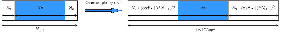
An oversampled signal is a signal sampled at a frequency that is higher than the Nyquist rate. WLAN signals maximize occupied bandwidth by using small guardbands, which can pose problems for anti-imaging and anti-aliasing filters. Oversampling increases the guardband width relative to the total signal bandwidth, thereby increasing the number of samples in the signal.

This function performs oversampling by using a larger IFFT and zero pad when generating an OFDM waveform. This diagram shows the oversampling process for an OFDM waveform with NFFT subcarriers comprising Ng guardband subcarriers on either side of Nst occupied bandwidth subcarriers.

FFT-based oversampling

Scrambler Initialization

The scrambler initialization used on the transmission data follows the process described in IEEE Std 802.11-2012, Section 18.3.5.5 and IEEE Std 802.11ad™-2012, Section 21.3.9. The header and data fields that follow the scrambler initialization field (including data padding bits) are scrambled by XORing each bit with a length-127 periodic sequence generated by the polynomial S(x) = x7+x4+1. The octets of the PSDU are placed into a bit stream and, within each octet, bit 0 (LSB) is first and bit 7 (MSB) is last. This figure shows the generation of the sequence and the XOR operation.

Generate a periodic sequence of length 127 by using the XOR operation

Conversion from integer to bits uses left-MSB orientation. For example, initializing the scrambler with decimal 1, the bits map to these elements.

ElementX7X6X5X4X3X2X1
Bit Value0000001

To generate the bit stream equivalent to a decimal, use the int2bit function. For example, for decimal 1:

int2bit(1,7)'
ans =

     0     0     0     0     0     0     1

References

[1] IEEE Std 802.11-2020 (Revision of IEEE Std 802.11-2016). “Part 11: Wireless LAN Medium Access Control (MAC) and Physical Layer (PHY) Specifications.” IEEE Standard for Information Technology — Telecommunications and Information Exchange between Systems — Local and Metropolitan Area Networks — Specific Requirements.

[2] IEEE Std 802.11ax™-2021 (Amendment to IEEE Std 802.11-2020). “Part 11: Wireless LAN Medium Access Control (MAC) and Physical Layer (PHY) Specifications. Amendment 1: Enhancements for High Efficiency WLAN.” IEEE Standard for Information Technology — Telecommunications and Information Exchange between Systems. Local and Metropolitan Area Networks — Specific Requirements.

Extended Capabilities

C/C++ Code Generation
Generate C and C++ code using MATLAB® Coder™.

Version History

Introduced in R2015b

expand all