Evaluate Wi-Fi 8 Co-TDMA Multi-AP Coordination Using System-Level Simulation
R2026bThis example compares the performance of multiple access point coordination (MAPC) with and without the use of IEEE® 802.11bn™ (Wi-Fi® 8) [1] coordinated time division multiple access (Co-TDMA).
Using this example, you can:
Establish Co-TDMA agreement between multiple access points (APs).
Visualize the packet communication in time and frequency domains for both scenarios.
Measure medium access control (MAC) throughput and 95 percentile (p95) latency metrics in both coordinated and uncoordinated scenarios.
Analyze Co-TDMA operational statistics at each AP.
Compare performance improvements from transmission opportunity (TXOP) sharing.
MAPC Framework
In dense deployments involving overlapping basic service sets (BSSs), a lack of coordination among APs can cause interference and performance degradation. WiFi-8 proposes an MAPC framework that enables multiple APs to coordinate their actions to improve efficiency and reliability. The MAPC framework involves different coordination schemes, including Co-TDMA, coordinated beamforming, coordinated spatial reuse, coordinated restricted target wake-time, and coordinated channel recommendation.
This example uses Co-TDMA, which focuses on sharing the TXOP owned by one AP with other APs, improving the chances of channel access in a congested network. The AP that owns the TXOP is the coordinating AP. The AP that responds to the coordinating AP and uses the TXOP shared by coordinating AP is the coordinated AP.
If multiple APs are competing for the channel and causing channel access delays, the probability of encountering worst case latency increases. Co-TDMA can help in reducing the probability of worst-case latency by improving the probability of channel access for any AP involved in MAPC.
System-Level Simulation Scenario
This example uses a network consisting of four BSSs. Each BSS has one AP and one STA. All AP and STA nodes are multilink devices (MLDs). Two links are associated with each MLD. Configure each BSS with downlink data traffic, enabling data flow from the AP to the STA.
Establish MAPC agreement between AP1 and AP2 for the Co-TDMA scheme, and leave AP3 and AP4 uncoordinated. Compare the results against an uncoordinated baseline scenario where all APs operate without Co-TDMA.
These figures depict the coordinated and uncoordinated network configurations.
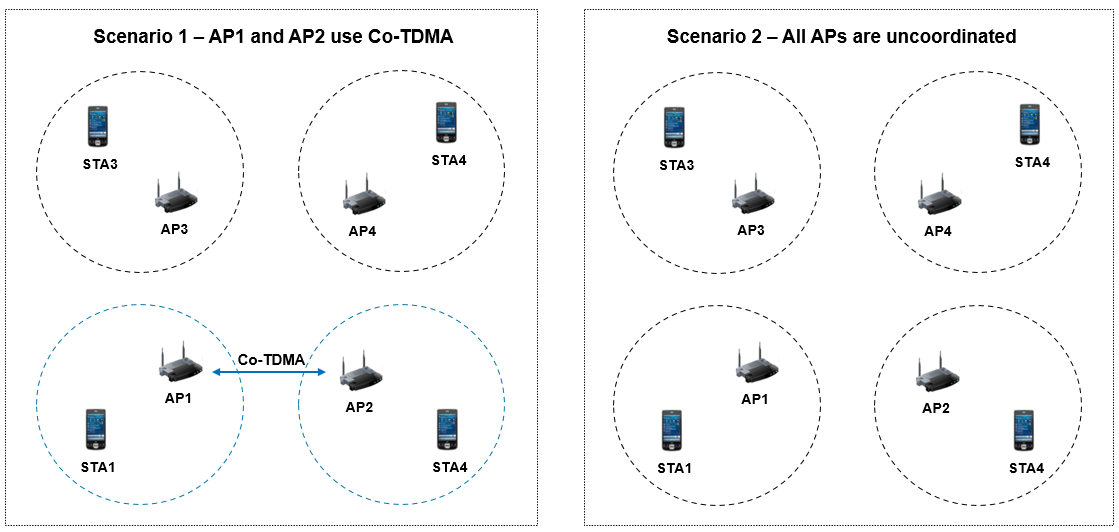
At the end of the simulation, compute the tail latency at each receiving STA and capture the operational statistics at each AP for the Co-TDMA mechanism.
Configure Common Simulation Parameters
Define the common parameters used in both simulation runs (with and without Co-TDMA).
Specify the simulation time in seconds. To visualize packet communication for all nodes, set the enablePacketVisualization variable to true.
simTime = 1.5;
enablePacketVisualization =  true;
true;Specify the application data traffic rate, application packet size, and node positions.
dataRate = 25e3;    % In Kbps
packetSize = 1000;  % In bytes
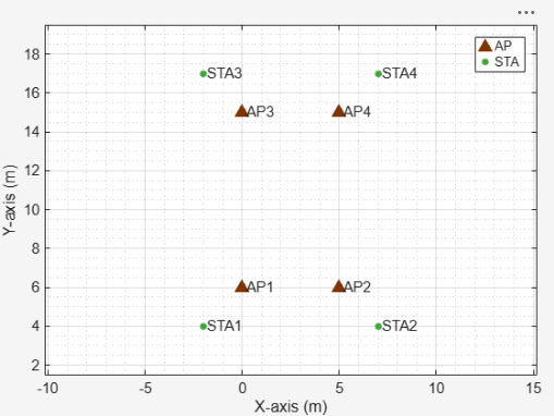
apPositions = {[0 6 0], [5 6 0], [0 15 3], [5 15 3]};    % In meters
staPositions = {[-2 4 0], [7 4 0], [-2 17 3], [7 17 3]}; % In meters
Configure the link settings for the MLDs. Create a common wlanLinkConfig object, specifying the BandAndChannel, TransmissionFormat, MCS, BeaconInterval, MPDUAggregationLimit, and TXOPLimit properties. Specify two [band,channel] pairs for the BandAndChannel property to create two wlanLinkConfig objects corresponding to the two links in each MLD.
commonLinkCfg = wlanLinkConfig(BandAndChannel=[5 36; 6 1],TransmissionFormat="EHT-SU",MCS=7,BeaconInterval=50,MPDUAggregationLimit=64,TXOPLimit=[0 0 120 60]);Create wlanMultilinkDeviceConfig objects for 802.11bn and 802.11be nodes and use them in both simulation scenarios.
apDevCfg11bn = wlanMultilinkDeviceConfig(StandardCapability="UHR",Mode="AP",LinkConfig=commonLinkCfg);
staDevCfg11bn = wlanMultilinkDeviceConfig(StandardCapability="UHR",Mode="STA",LinkConfig=commonLinkCfg);
apDevCfg11be = wlanMultilinkDeviceConfig(StandardCapability="EHT",Mode="AP",LinkConfig=commonLinkCfg);
staDevCfg11be = wlanMultilinkDeviceConfig(StandardCapability="EHT",Mode="STA",LinkConfig=commonLinkCfg);
Note that the physical layer (PHY) transmission format is set to extremely high throughput single user (EHT SU) for all the nodes, including nodes capable of the IEEE 802.11bn standard. The wireless local area network (WLAN) simulation does not currently support transmissions with ultra high reliability (UHR) PHY format. Since the EHT and UHR transmission formats use the same encoding for modulation and coding scheme (MCS) values 0 to 13, results obtained with EHT SU are comparable to those with UHR SU.
Simulate WLAN Scenario with Co-TDMA
Set the seed for the random number generator to 1. The seed value controls the pattern of random number generation. The random number generated by the seed value impacts several processes within the simulation, including backoff counter selection at the MAC layer and prediction of packet reception success at the physical layer. To improve the accuracy of your simulation results after running the simulation, you can change the seed value, run the simulation again, and average the results over multiple simulations.
rng(1,"twister");Initialize the wireless network simulator.
networkSimulator = wirelessNetworkSimulator.init;
Configure BSS
Create four BSSs, each containing one AP MLD and one STA MLD, using the wlanNode object. Specify the device configurations created in the Configure Common Simulation Parameters section through the DeviceConfig property of the wlanNode object. BSS1 and BSS2 use 802.11bn configurations (apDevCfg11bn and staDevCfg11bn) to enable Co-TDMA operation. BSS3 and BSS4 use 802.11be configurations (apDevCfg11be and staDevCfg11be) .
Associate each STA with its AP using the associateStations object function.
% BSS-1
ap1 = wlanNode(Name="AP1",Position=apPositions{1},DeviceConfig=apDevCfg11bn);
sta1 = wlanNode(Name="STA1",Position=staPositions{1},DeviceConfig=staDevCfg11bn);
associateStations(ap1,sta1);

% BSS-2
ap2 = wlanNode(Name="AP2",Position=apPositions{2},DeviceConfig=apDevCfg11bn);
sta2 = wlanNode(Name="STA2",Position=staPositions{2},DeviceConfig=staDevCfg11bn);
associateStations(ap2,sta2);

% BSS-3
ap3 = wlanNode(Name="AP3",Position=apPositions{3},DeviceConfig=apDevCfg11be);
sta3 = wlanNode(Name="STA3",Position=staPositions{3},DeviceConfig=staDevCfg11be);
associateStations(ap3,sta3);

% BSS-4
ap4 = wlanNode(Name="AP4",Position=apPositions{4},DeviceConfig=apDevCfg11be);
sta4 = wlanNode(Name="STA4",Position=staPositions{4},DeviceConfig=staDevCfg11be);
associateStations(ap4,sta4);

nodes = [ap1 sta1 ap2 sta2 ap3 sta3 ap4 sta4];
To visualize the node positions in the Cartesian plane, use the wirelessNetworkViewer object. Add the AP and the STA to the wirelessNetworkViewer object by using the addNodes object function.
networkViewerObj = wirelessNetworkViewer;
addNodes(networkViewerObj,[ap1 ap2 ap3 ap4],Type="AP");
addNodes(networkViewerObj,[sta1 sta2 sta3 sta4],Type="STA");
Configure Application Traffic
Add downlink traffic for the video access category at each AP using the addTrafficSource object function. Configure traffic with the data rate and packet size specified in the dataRate and packetSize variables using the networkTrafficOnOff object.
traffic = networkTrafficOnOff(OnTime=Inf,OffTime=0,DataRate=dataRate,PacketSize=packetSize);
addTrafficSource(ap1,traffic,DestinationNode=sta1,AccessCategory=2);
addTrafficSource(ap2,traffic,DestinationNode=sta2,AccessCategory=2);
addTrafficSource(ap3,traffic,DestinationNode=sta3,AccessCategory=2);
addTrafficSource(ap4,traffic,DestinationNode=sta4,AccessCategory=2);
Establish MAPC Agreement for Co-TDMA
Establish MAPC agreement between AP1 and AP2 for the Co-TDMA scheme using the establishMAPCAgreement object function.
establishMAPCAgreement([ap1 ap2],MAPCSchemes="Co-TDMA");Note that, although you preconfigure the MAPC agreement in the MATLAB simulation, an AP does not initiate Co‑TDMA polling unless it receives a beacon with a signal strength of at least –72 dBm. This requirement exists because the MAPC agreement occurs out of band, without any actual frame exchange in the simulation, so the simulation does not confirm AP reachability. By requiring beacon reception at or above this threshold, you ensure reachability before initiating Co‑TDMA polling and prevent repeated polling failures when APs seem reachable but are actually out of range.
Configure Wireless Channel
To model a random TGax fading channel between each node, this example uses the hSLSTGaxMultiFrequencySystemChannel helper object. Add the channel model to the wireless network simulator by using the addChannelModel object function of the wirelessNetworkSimulator object. By default, the hSLSTGaxMultiFrequencySystemChannel helper object models a stationary channel, meaning the scatterers in the environment have zero velocity.
channel = hSLSTGaxMultiFrequencySystemChannel(nodes);
addChannelModel(networkSimulator,channelFunction(channel))
Run Simulation and Analyze Results
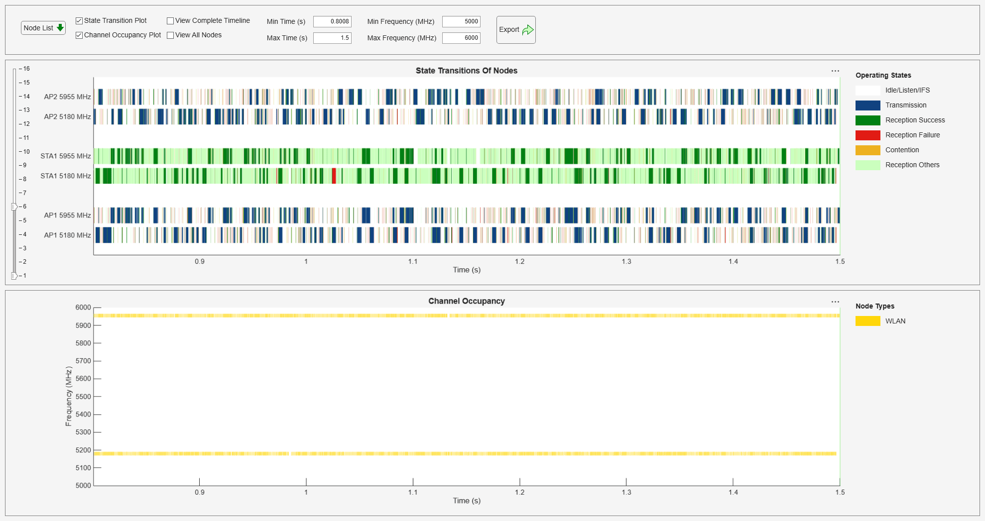
To visualize the packet communication, use the wirelessTrafficViewer object. The visualization shows these plots:
Packet communication over the time and frequency domains
State transitions of each node over time
Add the nodes to the wirelessTrafficViewer object by using the addNodes object function.
if enablePacketVisualization
    packetVisObj = wirelessTrafficViewer;
    addNodes(packetVisObj,nodes);
end
To view the node performance, use the helperPerformanceViewer helper object.
perfViewerObj_CoTDMA = helperPerformanceViewer(nodes,simTime);
Add all the nodes to the simulator and run the simulation for the specified time.
addNodes(networkSimulator,nodes);
run(networkSimulator,simTime);
Calculate the throughput values for each AP.
ap_throughput_CoTDMA = throughput(perfViewerObj_CoTDMA, [ap1.ID ap2.ID ap3.ID ap4.ID]);
disp("Throughputs with CoTDMA: AP1 = " + ap_throughput_CoTDMA(1) + "Mbps, AP2 = " + ap_throughput_CoTDMA(2) + ...
    "Mbps, AP3 = " + ap_throughput_CoTDMA(3) + "Mbps, AP4 = " + ap_throughput_CoTDMA(4) + "Mbps");
Throughputs with CoTDMA: AP1 = 24.992Mbps, AP2 = 24.7733Mbps, AP3 = 24.976Mbps, AP4 = 24.8533Mbps
Calculate the p95 latency values for each receiving station. You can also compute p99 latency by specifying 'P99' as the third argument of tailReceiveLatency object function.
sta_latencies_with_CoTDMA = tailReceiveLatency(perfViewerObj_CoTDMA, [sta1.ID sta2.ID sta3.ID sta4.ID],"P95")*1e3;
disp("P95 Latencies with CoTDMA: STA1 = " + sta_latencies_with_CoTDMA(1) + "(ms), STA2 = " + sta_latencies_with_CoTDMA(2) + ...
    "(ms), STA3 = " + sta_latencies_with_CoTDMA(3) + "(ms), STA4 = " + sta_latencies_with_CoTDMA(4) + "(ms)");
P95 Latencies with CoTDMA: STA1 = 24.949(ms), STA2 = 18.53(ms), STA3 = 18.1335(ms), STA4 = 22.4505(ms)
Co-TDMA Operational Statistics
You can observe the Co-TDMA operational statistics by calling the hGetCoTDMAOperationStatistics helper function. This function displays the operational statistics and also returns the same statistics in the form of a structure for the specified AP node in both the coordinating AP role and coordinated AP role.
The output ap1CoordinatingAPStats is an array of two structures corresponding to two links. Each structure holds statistics corresponding to Co-TDMA operation in the role of coordinating AP. Similarly, the output ap1CoordinatedAPStats is an array of two structures corresponding to two links. Each structure holds statistics corresponding to Co-TDMA operation in the role of coordinated AP.
You can infer from these operational statistics how many times an AP initiated Co-TDMA, how many times it initiated TXOP sharing, how many times it failed, and the reasons for the failures.
[ap1CoordinatingAPStats, ap1CoordinatedAPStats] = hGetCoTDMAOperationStatistics(ap1);
========================================================
Co-TDMA operation at AP with Node Name:AP1, Node ID:1
========================================================
=====================
Link-1 (5GHz, CH: 36)
=====================
Operation as a Coordinating AP:
-------------------------------
  Number of BSRP frames transmitted:              :109
  Number of Multi-STA BA responses received       :63
  Number of MU-RTS TXS Trigger frames transmitted :28
  Number of CTS responses received for MU-RTS TXS :28
  Number of MAPC TXOP Return frames received      :22
  Number of times Co-TDMA initiation was dropped due to -
      No beacon receptions (yet) with at least -72 dBm :0
      Insufficient TXOP limit                          :32
                                               (Total) :32
  Number of times TXOP sharing was dropped due to -
      Polling rejected            :1
      Fairness consideration      :7
      Insufficient remaining time :26
                          (Total) :34
  TXOP sharing success as % of Co-TDMA attempts   :25.6881%
  TXOP sharing drop as % of Co-TDMA attempts      :74.3119%
-------------------------------
Operation as a Coordinated AP:
-------------------------------
  Number of BSRP frames received                    :78
  Number of Multi-STA BA response transmitted       :78
  Number of MU-RTS TXS Trigger frames received      :31
  Number of CTS respones transmitted for MU-RTS TXS :31
  Number of MAPC TXOP Return frames transmitted     :22
  Number of times polling was rejected due to -
      No frames in queue to transmit                    :3
      Insufficient duration considered for TXOP sharing :0
                                                (Total) :3
  Poll acceptance as % of received BSRP frames      :96.1538%
  Poll rejection as % of received BSRP frames       :3.8462%
  Number of successful data transmissions in shared TXOP     :312
  Successful data transmissions in shared TXOP as % of total :13.0818%
=====================
Link-2 (6GHz, CH: 1)
=====================
Operation as a Coordinating AP:
-------------------------------
  Number of BSRP frames transmitted:              :118
  Number of Multi-STA BA responses received       :72
  Number of MU-RTS TXS Trigger frames transmitted :29
  Number of CTS responses received for MU-RTS TXS :29
  Number of MAPC TXOP Return frames received      :26
  Number of times Co-TDMA initiation was dropped due to -
      No beacon receptions (yet) with at least -72 dBm :0
      Insufficient TXOP limit                          :51
                                               (Total) :51
  Number of times TXOP sharing was dropped due to -
      Polling rejected            :3
      Fairness consideration      :7
      Insufficient remaining time :32
                          (Total) :42
  TXOP sharing success as % of Co-TDMA attempts   :24.5763%
  TXOP sharing drop as % of Co-TDMA attempts      :75.4237%
-------------------------------
Operation as a Coordinated AP:
-------------------------------
  Number of BSRP frames received                    :56
  Number of Multi-STA BA response transmitted       :56
  Number of MU-RTS TXS Trigger frames received      :16
  Number of CTS respones transmitted for MU-RTS TXS :16
  Number of MAPC TXOP Return frames transmitted     :15
  Number of times polling was rejected due to -
      No frames in queue to transmit                    :4
      Insufficient duration considered for TXOP sharing :0
                                                (Total) :4
  Poll acceptance as % of received BSRP frames      :92.8571%
  Poll rejection as % of received BSRP frames       :7.1429%
  Number of successful data transmissions in shared TXOP     :134
  Successful data transmissions in shared TXOP as % of total :5.8236%
[ap2CoordinatingAPStats, ap2CoordinatedAPStats] = hGetCoTDMAOperationStatistics(ap2);
========================================================
Co-TDMA operation at AP with Node Name:AP2, Node ID:3
========================================================
=====================
Link-1 (5GHz, CH: 36)
=====================
Operation as a Coordinating AP:
-------------------------------
  Number of BSRP frames transmitted:              :118
  Number of Multi-STA BA responses received       :74
  Number of MU-RTS TXS Trigger frames transmitted :31
  Number of CTS responses received for MU-RTS TXS :31
  Number of MAPC TXOP Return frames received      :22
  Number of times Co-TDMA initiation was dropped due to -
      No beacon receptions (yet) with at least -72 dBm :6
      Insufficient TXOP limit                          :41
                                               (Total) :47
  Number of times TXOP sharing was dropped due to -
      Polling rejected            :3
      Fairness consideration      :8
      Insufficient remaining time :30
                          (Total) :41
  TXOP sharing success as % of Co-TDMA attempts   :26.2712%
  TXOP sharing drop as % of Co-TDMA attempts      :73.7288%
-------------------------------
Operation as a Coordinated AP:
-------------------------------
  Number of BSRP frames received                    :64
  Number of Multi-STA BA response transmitted       :64
  Number of MU-RTS TXS Trigger frames received      :28
  Number of CTS respones transmitted for MU-RTS TXS :28
  Number of MAPC TXOP Return frames transmitted     :22
  Number of times polling was rejected due to -
      No frames in queue to transmit                    :1
      Insufficient duration considered for TXOP sharing :0
                                                (Total) :1
  Poll acceptance as % of received BSRP frames      :98.4375%
  Poll rejection as % of received BSRP frames       :1.5625%
  Number of successful data transmissions in shared TXOP     :281
  Successful data transmissions in shared TXOP as % of total :10.648%
=====================
Link-2 (6GHz, CH: 1)
=====================
Operation as a Coordinating AP:
-------------------------------
  Number of BSRP frames transmitted:              :112
  Number of Multi-STA BA responses received       :56
  Number of MU-RTS TXS Trigger frames transmitted :16
  Number of CTS responses received for MU-RTS TXS :16
  Number of MAPC TXOP Return frames received      :15
  Number of times Co-TDMA initiation was dropped due to -
      No beacon receptions (yet) with at least -72 dBm :2
      Insufficient TXOP limit                          :38
                                               (Total) :40
  Number of times TXOP sharing was dropped due to -
      Polling rejected            :4
      Fairness consideration      :7
      Insufficient remaining time :25
                          (Total) :36
  TXOP sharing success as % of Co-TDMA attempts   :14.2857%
  TXOP sharing drop as % of Co-TDMA attempts      :85.7143%
-------------------------------
Operation as a Coordinated AP:
-------------------------------
  Number of BSRP frames received                    :72
  Number of Multi-STA BA response transmitted       :72
  Number of MU-RTS TXS Trigger frames received      :29
  Number of CTS respones transmitted for MU-RTS TXS :29
  Number of MAPC TXOP Return frames transmitted     :26
  Number of times polling was rejected due to -
      No frames in queue to transmit                    :3
      Insufficient duration considered for TXOP sharing :0
                                                (Total) :3
  Poll acceptance as % of received BSRP frames      :95.8333%
  Poll rejection as % of received BSRP frames       :4.1667%
  Number of successful data transmissions in shared TXOP     :311
  Successful data transmissions in shared TXOP as % of total :15.5035%
Simulate WLAN Scenario without Co-TDMA
Reset the seed for the random number generator to 1 so that the generated random number stream is comparable to the first simulation run.
rng(1);
Initialize the wireless network simulator.
networkSimulator = wirelessNetworkSimulator.init;
Configure BSS
Create four BSSs, each containing one AP and one STA, using wlanNode objects. Configure all nodes as 802.11be by specifying apDevCfg11be and staDevCfg11be (from the Configure Common Simulation Parameters section) through the DeviceConfig property of the wlanNode object.
Associate each STA with its AP using the associateStations object function.
% BSS-1
ap1 = wlanNode(Name="AP1",Position=apPositions{1},DeviceConfig=apDevCfg11be);
sta1 = wlanNode(Name="STA1",Position=staPositions{1},DeviceConfig=staDevCfg11be);
associateStations(ap1,sta1);

% BSS-2
ap2 = wlanNode(Name="AP2",Position=apPositions{2},DeviceConfig=apDevCfg11be);
sta2 = wlanNode(Name="STA2",Position=staPositions{2},DeviceConfig=staDevCfg11be);
associateStations(ap2,sta2);

% BSS-3
ap3 = wlanNode(Name="AP3",Position=apPositions{3},DeviceConfig=apDevCfg11be);
sta3 = wlanNode(Name="STA3",Position=staPositions{3},DeviceConfig=staDevCfg11be);
associateStations(ap3,sta3);

% BSS-4
ap4 = wlanNode(Name="AP4",Position=apPositions{4},DeviceConfig=apDevCfg11be);
sta4 = wlanNode(Name="STA4",Position=staPositions{4},DeviceConfig=staDevCfg11be);
associateStations(ap4,sta4);

nodes = [ap1 sta1 ap2 sta2 ap3 sta3 ap4 sta4];
Configure Application Traffic
Add downlink traffic for the video access category at each AP using the addTrafficSource object function. Configure traffic with the data rate and packet size specified in the dataRate and packetSize variables using the networkTrafficOnOff object.
traffic = networkTrafficOnOff(OnTime=Inf,OffTime=0,DataRate=dataRate,PacketSize=packetSize);
addTrafficSource(ap1,traffic,DestinationNode=sta1,AccessCategory=2);
addTrafficSource(ap2,traffic,DestinationNode=sta2,AccessCategory=2);
addTrafficSource(ap3,traffic,DestinationNode=sta3,AccessCategory=2);
addTrafficSource(ap4,traffic,DestinationNode=sta4,AccessCategory=2);
Configure Wireless Channel
To model a random TGax fading channel between each node, this example uses the hSLSTGaxMultiFrequencySystemChannel helper object. Add the channel model to the wireless network simulator by using the addChannelModel object function of the wirelessNetworkSimulator object. By default, the hSLSTGaxMultiFrequencySystemChannel helper object models a stationary channel, meaning the scatterers in the environment have zero velocity.
channel = hSLSTGaxMultiFrequencySystemChannel(nodes);
addChannelModel(networkSimulator,channelFunction(channel))
Simulation and Results
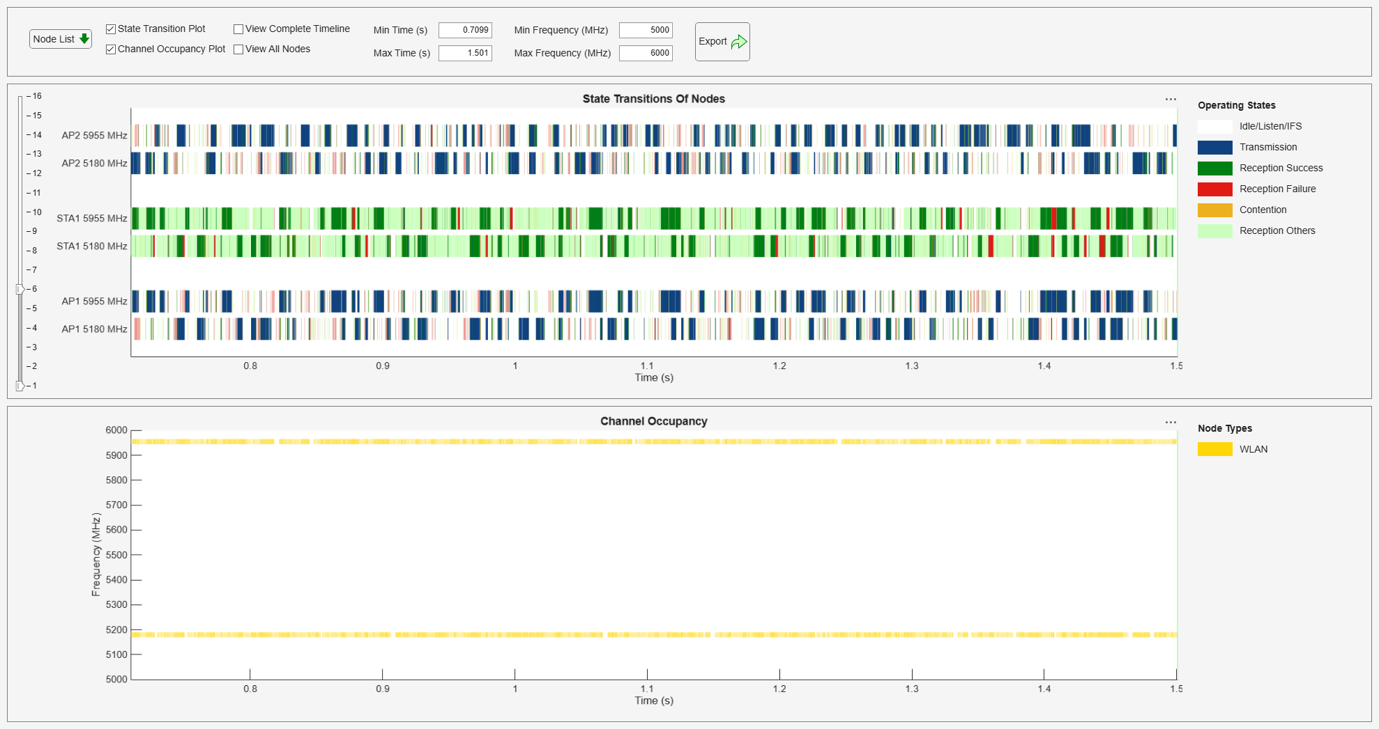
To visualize the packet communication, use the wirelessTrafficViewer object. The visualization shows these plots:
Packet communication over the time and frequency domains
State transitions of each node over time
Add the nodes to the wirelessTrafficViewer object by using the addNodes object function.
if enablePacketVisualization
    packetVisObj = wirelessTrafficViewer;
    addNodes(packetVisObj,nodes);
end
To view the node performance, use the helperPerformanceViewer helper object.
perfViewerObj_NoCoTDMA = helperPerformanceViewer(nodes,simTime);
Add all the nodes to the simulator and run the simulation for the specified time.
addNodes(networkSimulator,nodes);
run(networkSimulator,simTime);
Calculate the throughput values for each AP.
ap_throughput_without_CoTDMA = throughput(perfViewerObj_NoCoTDMA, [ap1.ID ap2.ID ap3.ID ap4.ID]);
disp("Throughputs without CoTDMA: AP1 = " + ap_throughput_without_CoTDMA(1) + "Mbps, AP2 = " + ap_throughput_without_CoTDMA(2) + ...
    "Mbps, AP3 = " + ap_throughput_without_CoTDMA(3) + "Mbps, AP4 = " + ap_throughput_without_CoTDMA(4) + "Mbps");
Throughputs without CoTDMA: AP1 = 24.912Mbps, AP2 = 24.944Mbps, AP3 = 24.9653Mbps, AP4 = 24.688Mbps
Calculate the p95 latency values for each receiving station and store the values for comparison. You can also compute p99 latency by specifying P99 as the third argument of the tailReceiveLatency object function.
sta_latencies_without_CoTDMA = tailReceiveLatency(perfViewerObj_NoCoTDMA, [sta1.ID sta2.ID sta3.ID sta4.ID],"P95")*1e3;
disp("P95 Latencies without CoTDMA: STA1 = " + sta_latencies_without_CoTDMA(1) + "(ms), STA2 = " + sta_latencies_without_CoTDMA(2) + ...
    "(ms), STA3 = " + sta_latencies_without_CoTDMA(3) + "(ms), STA4 = " + sta_latencies_without_CoTDMA(4) + "(ms)");
P95 Latencies without CoTDMA: STA1 = 20.3614(ms), STA2 = 19.1695(ms), STA3 = 16.9217(ms), STA4 = 23.2227(ms)
Compare P95 Latency Values
Plot the comparison of p95 latency values at each STA for scenarios with and without Co-TDMA.
plotLatencyComparison(sta_latencies_without_CoTDMA, sta_latencies_with_CoTDMA);
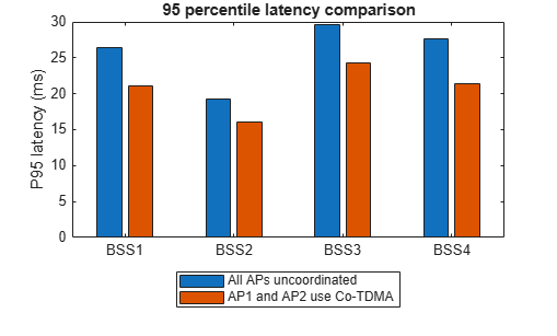
Notice that Co-TDMA operation between AP1 and AP2 results in balanced latency improvement at both APs. Importantly, this latency improvement does not come at the cost of throughput. Throughput changes between the two scenarios are minimal.
Considerations for Performance Analysis
If you configure a traffic load that exceeds the transmission capacity of the coordinating AP, its transmission queues can saturate. The default behavior in MATLAB is that a coordinating AP shares its TXOP with another AP only after it completes its own transmissions. So, even if the coordinating AP polls other APs, it cannot share the TXOP if it is occupied with its own transmissions. In such cases, polling introduces unnecessary overhead and increases latency.
You can monitor the number of times Co-TDMA initiation drops due to insufficient time or the number of times TXOP sharing drops (after polling phase) due to insufficient time. These metrics help you determine if the traffic load is too high.
If you set the traffic load too low for the coordinating AP to use at least 33% of its own TXOP, the coordinating AP might poll other APs but not share its TXOP. The fairness rule requires an AP to use at least 33% of the TXOP duration for its own transmissions before it can share the TXOP with other APs. A coordinating AP can ignore this rule if it has an MAPC agreement with all APs from which it receives a beacon with a signal strength of at least –72 dBm.
Co-TDMA works best when you configure the TXOP limit and traffic load so that the coordinating AP can often use at least 33% of the TXOP for its own transmissions and still have enough TXOP left to share with coordinated APs.
Appendix
This example uses these helper objects included as supporting files, to create a wireless channel model for the Wi-Fi network.
hSLSTGaxMultiFrequencySystemChannel— Creates a system channel objecthSLSTGaxAbstractSystemChannel— Creates a channel object for an abstracted PHY layerhSLSTGaxSystemChannel— Creates a channel object for a full PHY layerhSLSTGaxSystemChannelBase— Creates the base channel objecthelperPerformanceViewer— Return a performance metrics viewer objecthGetCoTDMAOperationStatistics— Display and return Co-TDMA operational statistics
References
[1] IEEE P802.11bn™/D1.4. Draft Standard for Information technology -Telecommunications and information exchange between systems Local and metropolitan area networks - Specific requirements. Part 11: Wireless LAN Medium Access Control (MAC) and Physical Layer (PHY) Specifications. Amendment 6: Enhancements for ultra-high reliability (UHR).
Local Functions
plotLatencyComparison
Plot and compare the latency values captured in the simulations with and without Co-TDMA.
function plotLatencyComparison(latencies_without_cotdma, latencies_with_cotdma)
    bar([latencies_without_cotdma' latencies_with_cotdma']);
    title("95 percentile latency comparison");
    xticklabels(["BSS1" "BSS2" "BSS3" "BSS4"]);
    ylabel("P95 latency (ms)");
    legend(["All APs uncoordinated" "AP1 and AP2 use Co-TDMA"], Location="southoutside");
end

