Image Transmission and Reception Using 802.11 Waveform and SDR
This example shows how to encode and pack an image file into WLAN packets for transmission and subsequently decode the packets to retrieve the image. The example also shows how to use a software-defined radio (SDR) for over-the-air transmission and reception of the WLAN packets.
Introduction
This example imports and segments an image file into multiple medium access control (MAC) service data units (MSDUs). It passes each MSDU to the wlanMACFrame function to create a MAC protocol data unit (MPDU). This function also utilizes a wlanMACFrameConfig object as an input, which sequentially numbers the MPDUs through the SequenceNumber property. The example then passes the MPDUs to the physical (PHY) layer as PHY Layer Service Data Units (PSDUs). Each PSDU uses a single non-high-throughput (non-HT), 802.11a™ WLAN packet for transmission. This example creates a WLAN baseband waveform using the wlanWaveformGenerator function. This function utilizes multiple PSDUs and processes each to form a series of physical layer convergence procedure (PLCP) protocol data units (PPDUs) ready for transmission.
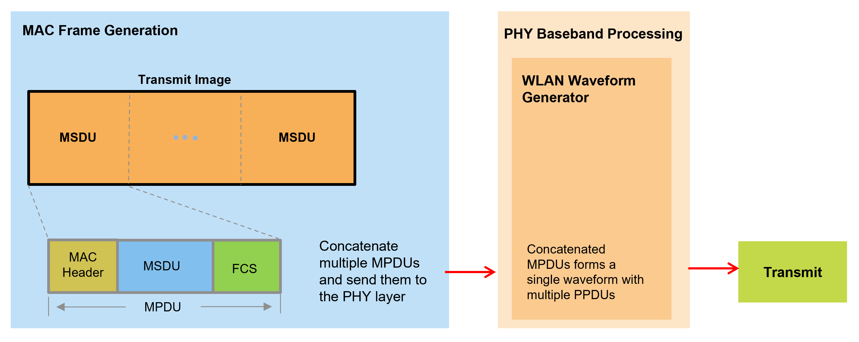
The generated waveform then passes through an additive white Gaussian noise (AWGN) channel to simulate an over-the-air transmission. Subsequently, the wlanMPDUDecode function takes the noisy waveform and decodes it. Then, the SequenceNumber property in the recovered MAC frame configuration object allows the example to sequentially order the extracted MSDUs. The information bits in the multiple received MSDUs combine to recover the transmitted image. This diagram shows the receiver processing.
![]()
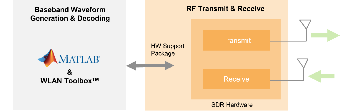
Alternatively, the generated WLAN waveform can be transmitted over the air and received using these supported SDRs.
Example Setup
Before running the example, set the channel variable to be one of these options:
OverTheAir: Use an SDR to transmit and receive the WLAN waveformGaussianNoise: Pass the transmission waveform through an AWGN channel (default)NoImpairments: Pass the transmission waveform through with no impairments
If you set channel to OverTheAir, set frequency band and channel, transmission gain, reception gain, and desired SDR:
Set to
Plutoto use the ADALM-Pluto from the Communications Toolbox Support Package for Analog Devices® ADALM-Pluto Radio (default)Set to B200 or B210 to use USRP™ B200/B210 radio from Communications Toolbox Support Package for USRP™ Radio
channel ="GaussianNoise"; if strcmpi(channel,"OverTheAir") deviceName =
"Pluto"; deviceAddress =
"usb:0"; channelNumber =
5; frequencyBand =
2.4; txGain =
-10 rxGain =
0 elseif strcmpi(channel,"GaussianNoise") % Specify SNR of received signal for a simulated channel SNR =
20; end
Configure all the scopes and figures for the example.
% Setup handle for image plot
if ~exist('imFig','var') || ~ishandle(imFig) %#ok<SUSENS>
    imFig = figure;
    imFig.NumberTitle = 'off';
    imFig.Name = 'Image Plot';
    imFig.Visible = 'off';
else
    clf(imFig); % Clear figure
    imFig.Visible = 'off';
end

% Setup Spectrum viewer
spectrumScope = spectrumAnalyzer( ...
    SpectrumType='power-density', ...
    Title='Received Baseband WLAN Signal Spectrum', ...
    YLabel='Power spectral density', ...
    Position=[69 376 800 450]);

% Setup the constellation diagram viewer for equalized WLAN symbols
refQAM = wlanReferenceSymbols('64QAM');
constellation = comm.ConstellationDiagram(...
    Title='Equalized WLAN Symbols',...
    ShowReferenceConstellation=true,...
    ReferenceConstellation=refQAM,...
    Position=[878 376 460 460]);
Transmitter Design
These steps describe the general procedure of the WLAN transmitter.
Import an image file and convert it to a stream of decimal bytes
Generate a baseband WLAN signal using the WLAN Toolbox
Pack the data stream into multiple 802.11a packets
If using an SDR, these steps describe the setup of the SDR transmitter.
Prepare the baseband signal for transmission using the SDR hardware
Send the baseband data to the SDR hardware for upsampling and continuous transmission at the desired center frequency
Prepare Image File
Read data from the image file, scale it for transmission, and convert it to a stream of decimal bytes. The scaling of the image reduces the quality by decreasing the size of the binary data stream.
The size of the binary data stream impacts the number of WLAN packets required for the transmission of the image data. The number of WLAN packets generated for transmission depends on these factors.
The image scaling, set when importing the image file
The length of the data carried in a packet, specified by the
msduLengthvariableThe modulation and coding scheme (MCS) value of the transmitted packet
The combination of the scaling factor and MSDU length determines the number of WLAN radio packets required for transmission. Setting scale to 0.2 and msduLength to 2304 requires the transmission of 11 WLAN radio packets. Increasing the scaling factor or decreasing the MSDU length will result in the transmission of more packets.
% Input an image file and convert to binary stream fileTx ='peppers.png'; % Image file name fData = imread(fileTx); % Read image data from file scale =
0.2; % Image scaling factor origSize = size(fData); % Original input image size scaledSize = max(floor(scale.*origSize(1:2)),1); % Calculate new image size heightIx = min(round(((1:scaledSize(1))-0.5)./scale+0.5),origSize(1)); widthIx = min(round(((1:scaledSize(2))-0.5)./scale+0.5),origSize(2)); fData = fData(heightIx,widthIx,:); % Resize image imsize = size(fData); % Store new image size txImage = fData(:); % Plot transmit image imFig.Visible = 'on'; subplot(211); imshow(fData); title('Transmitted Image'); subplot(212); title('Received image appears here...'); set(gca,'Visible','off');
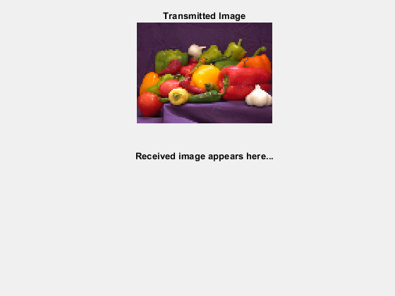
set(findall(gca, 'type', 'text'), 'visible', 'on');
Fragment Transmit Data
Split the data stream (txImage) into smaller transmit units (MSDUs) of size msduLength. Then, create an MPDU for each transmit unit using the wlanMACFrame function. Each call to this function creates an MPDU corresponding to the given MSDU and the frame configuration object. Next, create the frame configuration object using wlanMACFrameConfig to configure the sequence number of the MPDU. All the MPDUs are then sequentially passed to the physical layer for transmission.
To ensure that the MSDU size of the transmission does not exceed the standard-specified maximum, set the msduLength field to 2304 bytes. To make all MPDUs the same size, append zeros to the data in the last MPDU.
msduLength =2304; % MSDU length in bytes numMSDUs = ceil(length(txImage)/msduLength); padZeros = msduLength-mod(length(txImage),msduLength); txData = [txImage;zeros(padZeros,1)]; txDataBits = double(int2bit(txData,8,false)); % Divide input data stream into fragments bitsPerOctet = 8; data = zeros(0,1); for i=0:numMSDUs-1 % Extract image data (in octets) for each MPDU frameBody = txData(i*msduLength+1:msduLength*(i+1),:); % Create MAC frame configuration object and configure sequence number cfgMAC = wlanMACFrameConfig(FrameType='Data',SequenceNumber=i); % Generate MPDU [psdu, lengthMPDU]= wlanMACFrame(frameBody,cfgMAC,OutputFormat='bits'); % Concatenate PSDUs for waveform generation data = [data; psdu]; %#ok<AGROW> end
Generate 802.11a Baseband WLAN Signal
Synthesize a non-HT waveform using the wlanWaveformGenerator function with a non-HT format configuration object created by the wlanNonHTConfig object. In this example, the configuration object has a 20 MHz bandwidth, one transmit antenna and 64QAM rate 2/3 (MCS 6).
nonHTcfg = wlanNonHTConfig;       % Create packet configuration
nonHTcfg.MCS = 6;                 % Modulation: 64QAM Rate: 2/3
nonHTcfg.NumTransmitAntennas = 1; % Number of transmit antenna
chanBW = nonHTcfg.ChannelBandwidth;
nonHTcfg.PSDULength = lengthMPDU; % Set the PSDU length
Initialize the scrambler with a random integer for each packet.
scramblerInitialization = randi([1 127],numMSDUs,1);
Set the oversampling factor to 1.5 to generate the waveform at 30 MHz for transmission.
osf =1.5; sampleRate = wlanSampleRate(nonHTcfg); % Nominal sample rate in Hz % Generate baseband NonHT packets separated by idle time txWaveform = wlanWaveformGenerator(data,nonHTcfg, ... NumPackets=numMSDUs,IdleTime=20e-6, ... ScramblerInitialization=scramblerInitialization,... OversamplingFactor=osf);
Configure SDR Transmitter and Receiver Objects
The sdrTransmitter and sdrReceiver objects are created according to the selected radio type. The center frequency, sample rate, and gain values are assigned to these objects as appropriate.
For example, to transmit an 802.11a signal on channel 5 in the 2.4 GHz band, set the center frequency to 2.432 GHz, as specified in Section 16.3.6.3 of IEEE Std 802.11-2016.
if strcmpi(channel, "OverTheAir")
    % Determine the center frequency based on channel number and frequency band
    centerFrequency = wlanChannelFrequency(channelNumber, frequencyBand);

    % Initialize SDR transmitter and receiver objects with specified parameters
    [sdrTransmitter, sdrReceiver] = helperWLANGetSDRObjParams( ...
        deviceName, deviceAddress, txGain, rxGain, centerFrequency, sampleRate * osf);
end
Transmit Data
The sdrTransmitter object utilizes the transmitRepeat function to continuously transmit the baseband WLAN waveform.
For ADALM-PLUTO Radio:The
transmitRepeatfunction uploads the baseband WLAN waveform, including idle periods, to the SDR’s onboard DDR memory. The radio then continuously transmits the stored waveform over the air until you release the transmitter object.For USRP B200/B210 Radios:The
transmitRepeatfunction streams the WLAN waveform continuously in the background. Transmission continues until you explicitly call thestopTransmissionmethod on the transmitter object.
if strcmpi(channel, "OverTheAir")
    fprintf('\nGenerating WLAN transmit waveform...\n');

    % Scale the waveform to prevent RF front-end saturation
    powerScaleFactor = 0.8;
    txWaveform = txWaveform / max(abs(txWaveform)) * powerScaleFactor;

    % Transmit the waveform continuously using SDR hardware
    transmitRepeat(sdrTransmitter, txWaveform);

    % Allow additional setup time for specific USRP devices
    if any(strcmpi(deviceName, {'B200', 'B210'}))
        pause(12); % Extra delay for creating the driver in USRP and to initialize transmission
    end
end
Receiver Design
The steps listed below describe the general structure of the WLAN receiver.
If using SDR hardware, capture multiple packets of the transmitted WLAN signal
Detect a packet
Coarse carrier frequency offset is estimated and corrected
Fine timing synchronization is established. The L-STF, L-LTF and L-SIG samples are provided for fine timing to allow to adjust the packet detection at the start or end of the L-STF
Fine carrier frequency offset is estimated and corrected
Perform a channel estimation for the received signal using the L-LTF
Detect the format of the packet
Decode the L-SIG field to recover the MCS value and the length of the data portion
Decode the data field to obtain the transmitted data within each packet
Decode the received PSDU and check if the frame check sequence (FCS) passed for the PSDU
Order the decoded MSDUs based on the
SequenceNumberproperty in the recovered MAC frame configuration objectCombine the decoded MSDUs from all the transmitted packets to form the received image
This example plots the power spectral density (PSD) of the received waveform, and shows visualizations of the equalized data symbols and the received image.
Capture Data
If using an SDR, acquire the received signal by calling the capture method of the sdrReceiver object.
Otherwise, apply gaussian noise to the txWaveform using the awgn function or pass the txWaveform straight through to receiver processing.
if strcmpi(channel,"OverTheAir")

    % Configure the capture length equivalent to twice the length of the
    % transmitted signal, this is to ensure that PSDUs are received in order.
    % On reception the duplicate MAC fragments are removed.
    sdrReceiver.SamplesPerFrame = 2*length(txWaveform);
    fprintf('\nStarting a new RF capture.\n')

    rxWaveform = capture(sdrReceiver,sdrReceiver.SamplesPerFrame,'Samples');
elseif strcmpi(channel,"GaussianNoise")
    rxWaveform = awgn(txWaveform,SNR,'measured');
else % No Impairments
    rxWaveform = txWaveform;
end
Show the power spectral density of the received waveform.
spectrumScope.SampleRate = sampleRate*osf;
spectrumScope(rxWaveform);
release(spectrumScope);
![]()
Receiver Processing
Design a rate conversion filter for resampling the waveform to the nominal baseband rate for receiver processing using the designMultirateFIR function.
aStop = 40; % Stopband attenuation
ofdmInfo = wlanNonHTOFDMInfo('NonHT-Data',nonHTcfg); % OFDM parameters
SCS = sampleRate/ofdmInfo.FFTLength; % Subcarrier spacing
txbw = max(abs(ofdmInfo.ActiveFrequencyIndices))*2*SCS; % Occupied bandwidth
[L,M] = rat(1/osf);
maxLM = max([L M]);
R = (sampleRate-txbw)/sampleRate;
TW = 2*R/maxLM; % Transition width
b = designMultirateFIR(L,M,TW,aStop);
Resample the oversampled waveform back to 20 MHz for processing using the dsp.FIRRateConverter System object and the filter designed above.
firrc = dsp.FIRRateConverter(L,M,b);
rxWaveform = firrc(rxWaveform);
If using an SDR, the SDR continuously transmits the 802.11 waveform over-the-air in a loop. The first packet received by the sdrReceiver may not be the first transmitted packet. This means that the packets may be decoded out of sequence. To enable the received packets to be recombined in the correct order, their sequence number must be determined. The wlanMPDUDecode function decodes the MPDU from the decoded PSDU bits of each packet and outputs the MSDU as well as the recovered MAC frame configuration object wlanMACFrameConfig. The SequenceNumber property in the recovered MAC frame configuration object can be used for ordering the MSDUs in the transmitted sequence.
To display each packet's decoded L-SIG contents, the EVM measurements, and sequence number, check the displayFlag box.
displayFlag =  false;
 Set up required variables for receiver processing.
rxWaveformLen = size(rxWaveform,1);
searchOffset = 0; % Offset from start of the waveform in samples
Get the required field indices within a PSDU.
ind = wlanFieldIndices(nonHTcfg);
Ns = ind.LSIG(2)-ind.LSIG(1)+1; % Number of samples in an OFDM symbol

% Minimum packet length is 10 OFDM symbols
lstfLen = double(ind.LSTF(2)); % Number of samples in L-STF
minPktLen = lstfLen*5;
pktInd = 1;
fineTimingOffset = [];
packetSeq = [];
rxBit = [];

% Perform EVM calculation
evmCalculator = comm.EVM(AveragingDimensions=[1 2 3]);
evmCalculator.MaximumEVMOutputPort = true;
Use a while loop to process the received out-of-order packets.
while (searchOffset+minPktLen)<=rxWaveformLen
    % Packet detect
    pktOffset = wlanPacketDetect(rxWaveform,chanBW,searchOffset,0.5);

    % Adjust packet offset
    pktOffset = searchOffset+pktOffset;
    if isempty(pktOffset) || (pktOffset+double(ind.LSIG(2))>rxWaveformLen)
        if pktInd==1
            disp('** No packet detected **');
        end
        break;
    end

    % Extract non-HT fields and perform coarse frequency offset correction
    % to allow for reliable symbol timing
    nonHT = rxWaveform(pktOffset+(ind.LSTF(1):ind.LSIG(2)),:);
    coarseFreqOffset = wlanCoarseCFOEstimate(nonHT,chanBW);
    nonHT = frequencyOffset(nonHT,sampleRate,-coarseFreqOffset);

    % Symbol timing synchronization
    fineTimingOffset = wlanSymbolTimingEstimate(nonHT,chanBW);

    % Adjust packet offset
    pktOffset = pktOffset+fineTimingOffset;

    % Timing synchronization complete: Packet detected and synchronized
    % Extract the non-HT preamble field after synchronization and
    % perform frequency correction
    if (pktOffset<0) || ((pktOffset+minPktLen)>rxWaveformLen)
        searchOffset = pktOffset+1.5*lstfLen;
        continue;
    end
    fprintf('\nPacket-%d detected at index %d\n',pktInd,pktOffset+1);

    % Extract first 7 OFDM symbols worth of data for format detection and
    % L-SIG decoding
    nonHT = rxWaveform(pktOffset+(1:7*Ns),:);
    nonHT = frequencyOffset(nonHT,sampleRate,-coarseFreqOffset);

    % Perform fine frequency offset correction on the synchronized and
    % coarse corrected preamble fields
    lltf = nonHT(ind.LLTF(1):ind.LLTF(2),:);           % Extract L-LTF
    fineFreqOffset = wlanFineCFOEstimate(lltf,chanBW);
    nonHT = frequencyOffset(nonHT,sampleRate,-fineFreqOffset);
    cfoCorrection = coarseFreqOffset+fineFreqOffset; % Total CFO

    % Channel estimation using L-LTF
    lltf = nonHT(ind.LLTF(1):ind.LLTF(2),:);
    demodLLTF = wlanLLTFDemodulate(lltf,chanBW);
    chanEstLLTF = wlanLLTFChannelEstimate(demodLLTF,chanBW);

    % Noise estimation
    noiseVarNonHT = wlanLLTFNoiseEstimate(demodLLTF);

    % Packet format detection using the 3 OFDM symbols immediately
    % following the L-LTF
    format = wlanFormatDetect(nonHT(ind.LLTF(2)+(1:3*Ns),:), ...
        chanEstLLTF,noiseVarNonHT,chanBW);
    disp(['  ' format ' format detected']);
    if ~strcmp(format,'Non-HT')
        fprintf('  A format other than Non-HT has been detected\n');
        searchOffset = pktOffset+1.5*lstfLen;
        continue;
    end

    % Recover L-SIG field bits
    [recLSIGBits,failCheck] = wlanLSIGRecover( ...
        nonHT(ind.LSIG(1):ind.LSIG(2),:), ...
        chanEstLLTF,noiseVarNonHT,chanBW);

    if failCheck
        fprintf('  L-SIG check fail \n');
        searchOffset = pktOffset+1.5*lstfLen;
        continue;
    else
        fprintf('  L-SIG check pass \n');
    end

    % Retrieve packet parameters based on decoded L-SIG
    [lsigMCS,lsigLen,rxSamples] = helperInterpretLSIG(recLSIGBits,sampleRate);

    if (rxSamples+pktOffset)>length(rxWaveform)
        disp('** Not enough samples to decode packet **');
        break;
    end

    % Apply CFO correction to the entire packet
    rxWaveform(pktOffset+(1:rxSamples),:) = frequencyOffset(...
        rxWaveform(pktOffset+(1:rxSamples),:),sampleRate,-cfoCorrection);

    % Create a receive Non-HT config object
    rxNonHTcfg = wlanNonHTConfig;
    rxNonHTcfg.MCS = lsigMCS;
    rxNonHTcfg.PSDULength = lsigLen;

    % Get the data field indices within a PPDU
    indNonHTData = wlanFieldIndices(rxNonHTcfg,'NonHT-Data');

    % Recover PSDU bits using transmitted packet parameters and channel
    % estimates from L-LTF
    [rxPSDU,eqSym] = wlanNonHTDataRecover(rxWaveform(pktOffset+...
        (indNonHTData(1):indNonHTData(2)),:), ...
        chanEstLLTF,noiseVarNonHT,rxNonHTcfg);

    constellation(reshape(eqSym,[],1)); % Current constellation
    release(constellation);

    refSym = wlanClosestReferenceSymbol(eqSym,rxNonHTcfg);
    [evm.RMS,evm.Peak] = evmCalculator(refSym,eqSym);

    % Decode the MPDU and extract MSDU
    [cfgMACRx,msduList{pktInd},status] = wlanMPDUDecode(rxPSDU,rxNonHTcfg); %#ok<*SAGROW>

    if strcmp(status,'Success')
        disp('  MAC FCS check pass');

        % Store sequencing information
        packetSeq(pktInd) = cfgMACRx.SequenceNumber;

        % Convert MSDU to a binary data stream
        rxBit{pktInd} = int2bit(hex2dec(cell2mat(msduList{pktInd})),8,false);

    else % Decoding failed
        if strcmp(status,'FCSFailed')
            % FCS failed
            disp('  MAC FCS check fail');
        else
            % FCS passed but encountered other decoding failures
            disp('  MAC FCS check pass');
        end

        % Since there are no retransmissions modeled in this example, we
        % extract the image data (MSDU) and sequence number from the MPDU,
        % even though FCS check fails.

        % Remove header and FCS. Extract the MSDU.
        macHeaderBitsLength = 24*bitsPerOctet;
        fcsBitsLength = 4*bitsPerOctet;
        msduList{pktInd} = rxPSDU(macHeaderBitsLength+1:end-fcsBitsLength);

        % Extract and store sequence number
        sequenceNumStartIndex = 23*bitsPerOctet+1;
        sequenceNumEndIndex = 25*bitsPerOctet-4;
        conversionLength = sequenceNumEndIndex-sequenceNumStartIndex+1;
        packetSeq(pktInd) = bit2int(rxPSDU(sequenceNumStartIndex:sequenceNumEndIndex),conversionLength,false);

        % MSDU binary data stream
        rxBit{pktInd} = double(msduList{pktInd});
    end

    % Display decoded information
    if displayFlag
        fprintf('  Estimated CFO: %5.1f Hz\n\n',cfoCorrection); %#ok<*UNRCH>

        disp('  Decoded L-SIG contents: ');
        fprintf('                            MCS: %d\n',lsigMCS);
        fprintf('                         Length: %d\n',lsigLen);
        fprintf('    Number of samples in packet: %d\n\n',rxSamples);

        fprintf('  EVM:\n');
        fprintf('    EVM peak: %0.3f%%  EVM RMS: %0.3f%%n\n', ...
            evm.Peak,evm.RMS);

        fprintf('  Decoded MAC Sequence Control field contents:\n');
        fprintf('    Sequence number: %d\n\n',packetSeq(pktInd));
    end

    % Update search index
    searchOffset = pktOffset+double(indNonHTData(2));

    % Finish processing when a duplicate packet is detected. The
    % recovered data includes bits from duplicate frame
    % Remove the data bits from the duplicate frame
    if length(unique(packetSeq)) < length(packetSeq)
        rxBit = rxBit(1:length(unique(packetSeq)));
        packetSeq = packetSeq(1:length(unique(packetSeq)));
        break
    end

    pktInd = pktInd+1;
end
Packet-1 detected at index 7
Non-HT format detected
L-SIG check pass
MAC FCS check pass
Packet-2 detected at index 8647
Non-HT format detected
L-SIG check pass
MAC FCS check pass
Packet-3 detected at index 17287
Non-HT format detected
L-SIG check pass
MAC FCS check pass
Packet-4 detected at index 25927
Non-HT format detected
L-SIG check pass
MAC FCS check pass
Packet-5 detected at index 34567
Non-HT format detected
L-SIG check pass
MAC FCS check pass
Packet-6 detected at index 43207
Non-HT format detected
L-SIG check pass
MAC FCS check pass
Packet-7 detected at index 51847
Non-HT format detected
L-SIG check pass
MAC FCS check pass
Packet-8 detected at index 60487
Non-HT format detected
L-SIG check pass
MAC FCS check pass
Packet-9 detected at index 69127
Non-HT format detected
L-SIG check pass
MAC FCS check pass
Packet-10 detected at index 77767
Non-HT format detected
L-SIG check pass
MAC FCS check pass
Packet-11 detected at index 86407
Non-HT format detected
L-SIG check pass
![]()
MAC FCS check pass
If using an SDR, release the sdrTransmitter and sdrReceiver objects to stop the continuous transmission of the 802.11 waveform and to allow for any modification of the SDR object properties.
if strcmpi(channel,"OverTheAir")
    if ~strcmpi(deviceName, 'Pluto')
        stopTransmission(sdrTransmitter);
    end
    release(sdrTransmitter);
    release(sdrReceiver);
end
Reconstruct Image
Reconstruct the image using the received MAC frames.
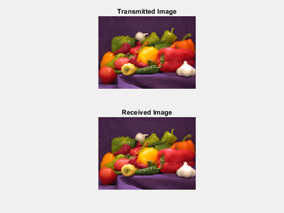
if ~(isempty(fineTimingOffset) || isempty(pktOffset))

    % Convert decoded bits from cell array to column vector
    rxData = cat(1,rxBit{:});
    % Remove any extra bits
    rxData = rxData(1:end-(mod(length(rxData),msduLength*8)));
    % Reshape such that each column length has bits equal to msduLength*8
    rxData = reshape(rxData,msduLength*8,[]);

    % Remove duplicate packets if any. Duplicate packets are located at the
    % end of rxData
    if length(packetSeq)>numMSDUs
        numDupPackets = size(rxData,2)-numMSDUs;
        rxData = rxData(:,1:end-numDupPackets);
    end

    % Initialize variables for while loop
    startSeq = [];
    i=-1;

    % Only execute this if one of the packet sequence values have been decoded
    % accurately
    if any(packetSeq<numMSDUs)
        while isempty(startSeq)
            % This searches for a known packetSeq value
            i = i + 1;
            startSeq = find(packetSeq==i);
        end
        % Circularly shift data so that received packets are in order for image reconstruction. It
        % is assumed that all packets following the starting packet are received in
        % order as this is how the image is transmitted.
        rxData = circshift(rxData,[0 -(startSeq(1)-i-1)]); % Order MAC fragments

        % Perform bit error rate (BER) calculation on reordered data
        bitErrorRate = comm.ErrorRate;
        err = bitErrorRate(double(rxData(:)), ...
            txDataBits(1:length(reshape(rxData,[],1))));
        fprintf('  \nBit Error Rate (BER):\n');
        fprintf('          Bit Error Rate (BER) = %0.5f\n',err(1));
        fprintf('          Number of bit errors = %d\n',err(2));
        fprintf('    Number of transmitted bits = %d\n\n',length(txDataBits));
    end

    decData = bit2int(reshape(rxData(:),8,[]),8,false)';

    % Append NaNs to fill any missing image data
    if length(decData)<length(txImage)
        numMissingData = length(txImage)-length(decData);
        decData = [decData;NaN(numMissingData,1)];
    else
        decData = decData(1:length(txImage));
    end

    % Recreate image from received data
    fprintf('\nConstructing image from received data.\n');
    receivedImage = uint8(reshape(decData,imsize));
    % Plot received image
    if exist('imFig','var') && ishandle(imFig) % If Tx figure is open
        figure(imFig); subplot(212);
    else
        figure; subplot(212);
    end
    imshow(receivedImage);
    title(sprintf('Received Image'));
end
Bit Error Rate (BER):
Bit Error Rate (BER) = 0.00000
Number of bit errors = 0
Number of transmitted bits = 202752
Constructing image from received data.
Further Exploration
If using an SDR, modify
txGainorrxGainto observe the difference in the EVM and BER after signal reception and processing. You may see errors in the displayed, received image.If running the example without an SDR, modify
SNRto observe the difference in the EVM and BER after signal reception and processing.Increase the scaling factor (
scale) to improve the quality of the received image by generating more transmit bits. This also increases the number of transmitted PPDUs.Decrease MSDU size (
msduLength) to decrease the number of bits transmitted per packet and observe the differences in EVM and BER when a signal is received with a lower SNR.
SDR Troubleshooting
ADALM-PLUTO Radio Common Problems and Fixes
USRP B200/B210 Radio Common Problems and Fixes