Model-Based Design of Communication Protocols for Deployment on FPGAs
By Hung Nguyen, Sandia National Laboratories; William Marchetto, Sandia National Laboratories; Roger Theyyunni, MathWorks; and Babak Soheili, MathWorks
To reduce development costs for embedded systems while speeding up development and maintaining reliability, the industry has moved towards reconfigurable architectures that can adapt to future mission requirements and handle system failures. These reconfigurable subsystems are usually based on resource-constrained FPGA hardware or on full-fledged, multi-processor systems with specialized DSPs.
Targeting FPGAs requires development in Verilog® or VHDL®, whereas targeting a processor requires development in C/C++. Many algorithms and components, particularly those related to communication, must be targeted to both processor-based and FPGA-based subsystems.
Sandia National Laboratories initiated a project with MathWorks consultants to evaluate Model-Based Design for such applications. Model-Based Design would enable them to generate C/C++ or HDL from block diagrams and deploy the same algorithms to both processor-based and FPGA-based subsystems. The project involved implementing two standardized communication protocols, Joint Architecture Standard Packet Protocol (JPP) and Joint Architecture Standard Reliable Data Delivery Protocol (JRDDP), on an FPGA. JPP and JRDDP are high-level protocols layered on top of SpaceWire, a widely used physical protocol layer for inter-module communications in embedded systems. Sandia National Laboratories used a hand-coded version of these protocols to evaluate the implementation developed with Model-Based Design.
This article describes the project, focusing on the model architecture and the verification techniques used. It demonstrates that Model-Based Design is a very good fit for protocol implementation.
Design Requirements
The JPP and JRDDP communication protocols specify how data is to be transmitted from a source node to a target node. They specify the format of the packet and the order in which the packets are to be transmitted and re-transmitted.
Because the activities required to implement these protocols are predefined and sequential, state machines were a logical choice. We decided to use Simulink® and Stateflow® to implement the state machines for modeling and generating C and HDL code for these protocols.
Model Architecture
The project involved developing JPP and JRDDP models with Simulink and Stateflow. As a best-effort protocol, JPP only required a transmitter block and a receiver block. JRDDP was more complicated. As a reliable packet transmission protocol used for guaranteed data delivery between applications, it required blocks for transmitting and receiving both data packets and control packets.
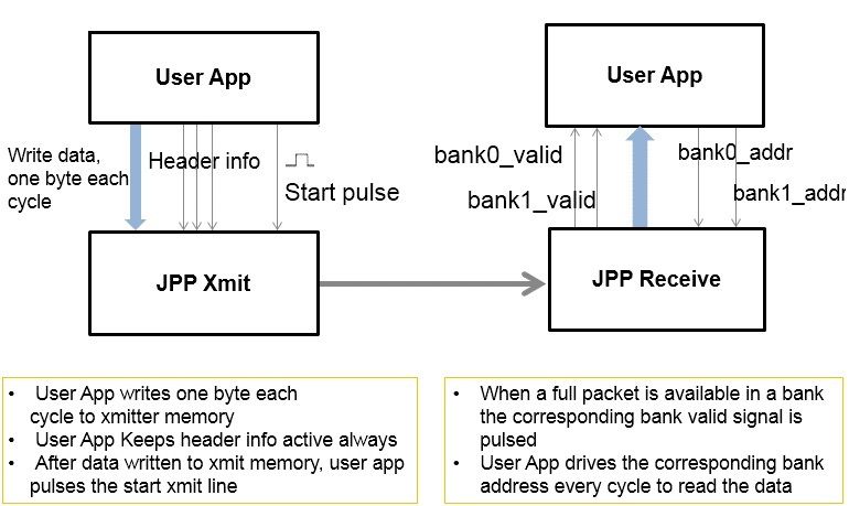
The blocks developed for this project were optimized for implementation on hardware (an FPGA). The user application must stream data bytes to and from the blocks at the operating clock frequency. The transmitter block provides a dual-ported RAM block into which the user application streams data before toggling a start transmission signal.
The receiver block maintains two banks of dual-ported RAM into which the received data is streamed as it arrives. When a full packet is available, a signal is pulsed to inform the user application that a complete packet is available in the corresponding bank.
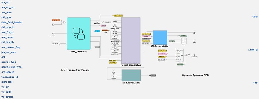
All transmitter blocks have similar structures. Figure 2 shows the top-level architecture for the JPP transmitter block.
The transmitter block connects to the user application at one end and to a SpaceWire interface at the other.
Receiver blocks have a similar structure (Figure 3).
Figure 4 shows a complete application using the JPP protocol to send and receive data.
Implementing Higher Level JRDDP Protocol
As a high-level protocol, JRDDP is more challenging to model than JPP. JRDDP defines communication between a transmit endpoint and a receive endpoint connected to each other during the initialization phase. A node can have multiple transmit and receive endpoints. A complete JRDDP endpoint requires putting the basic JRDDP blocks together and scheduling them.
To illustrate the process we developed an example transmitter with two transmit endpoints and an example receiver with two receive endpoints.
JRDDP defines the different states through which an endpoint must transition. The initial state of an end-point is “Closed.” When the user application requests that the endpoint open, the endpoint transitions to an “Enabled” state where the end-point sends an open request to a remote endpoint. On receiving acknowledgement, the end-point transitions to the “Open” state. In the “Open” state, the user application can transmit data to the remote node.
Model-Based Design enabled us to capture this complex process in a Stateflow diagram (Figure 5).
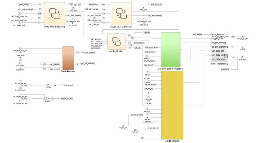
A complete JRDDP implementation entails maintaining JRDDP state machines for each endpoint and using JRDDP building blocks: a JRDDP transmitter block, a JRDDP receiver block, and a JRDDP control and acknowledge packet block. We needed to create Simulink and Stateflow blocks to route data from the SpaceWire interface to the state machine for the appropriate endpoint and from the state machine for the endpoint to the SpaceWire interface.
Figure 6 shows a JRDDP endpoint implementation for two transmit endpoints. At the top are two JRDDP state machines, one for each endpoint. The central Stateflow chart is a packet router to route control and data packets from each state machine to the control or data transmitter block. The diagram includes a data receiver that routes the received packet to the appropriate end-point state machine.
Integrating Sandia IP for a SpaceWire Interface
Sandia has developed VHDL intellectual property (IP) to create SpaceWire receiver and transmitter endpoints. It was important for Sandia to evaluate how easily this IP, used in production for several years, would integrate into the HDL generated with HDL Coder™ from the Simulink model.
Simulink enables blackboxing, the creation of subsystems containing only interface ports for instantiating hand-written entities. The engineer can associate the empty subsystem with an external VHDL entity or Verilog Module. We used blackboxing to interface Sandia’s SpaceWire IP with our Simulink model to develop complete JPP and JRDDP protocol interfaces. We also used blackboxing to test the Simulink generated JPP interface against Sandia’s hand-coded JPP protocol implementation.
Verification and Testing
Developing protocols in Simulink provides several benefits, in particular, the ability to test the protocol at a very high level. Debugging at this level is cheaper, easier, and faster than debugging in hardware or hardware simulators. We completed our verification in five steps:
- We simulated the transmission and reception of messages in Simulink. To do this we created a functional model of the SpaceWire interface in Stateflow. Simulink allows high-level debugging by letting the user breakpoint at the block level, in Stateflow states, and during state transitions. In addition, Simulink enables animation of the state transitions, providing visual verification that the model is behaving as desired.
- We used HDL Verifier™ to cosimulate the generated VHDL with the Simulink model to prove that the VHDL generated from Simulink produced the same results as the original Simulink model. For this, HDL Verifier automatically compares the results and plots the errors. In this step, we used Stateflow to emulate the SpaceWire interface; we did not use the actual SpaceWire IP.
- We again used cosimulation, replacing our functional model for SpaceWire with Sandia’s IP for the SpaceWire interface. We applied the cosimulation model to drive test inputs in ModelSim and captured the results in Simulink.
- We replaced the receiver with Sandia’s hand-coded implementation of the JPP receiver.
- We replaced the JPP receiver developed in Simulink and Stateflow with the Sandia VHDL JPP receiver and ran another cosimulation test. The test confirmed that the two JPP receivers are interchangeable.
Conclusions
This project confirmed that Model-Based Design could be used to model and realize high-level protocols in software and hardware. Modeling protocols in Simulink and Stateflow yields several benefits. First, the model provides an unambiguous executable specification for the protocols. Second, automatic C/C++ and HDL generation facilitates rapid development of reference implementations.
Another significant benefit of Model-Based Design is the ability to debug and verify the implementation in a high-level software environment. Simulink and Stateflow allow the setting of breakpoints in states and state transitions at the block and signal levels. Stateflow also facilitates debugging hierarchical state machines by animating the state transitions. After high-level debugging, co-simulation and FPGA-in-the-loop simulation provide debugging and verification of the design.
For the JPP implementation, HDL resource utilization in ML507 (a Virtex® 5-based board) was about 1%. For the JRDDP protocol, resource utilization was about 10% for a two-endpoint implementation. Further optimization and tuning will further reduce the resource utilization. Direct comparison with the hand-coded implementation was not possible because the hand-coded version was not implemented for the Xilinx® platform, but the resource utilization for the HDL generated from the Simulink and Stateflow model was acceptable to Sandia.
In Model-Based Design, the same Simulink model can generate both C/C++ for deployment on a processor and HDL for deployment on hardware (FPGA or ASIC). Both HDL and C/C++ can be generated from the same model, but the Simulink model must be optimized separately for each implementation by using Simulink features such as variant subsystems. For a processor-based implementation, the user application is likely to create a data frame and pass it to the protocol layer, which will process the frame as a whole, not as a byte stream. A hardware-based implementation receives data from the user application one byte at a time at the clock frequency of the hardware.
Modeling in a high-level language such as Simulink and Stateflow allows engineers who are not hardware specialists to create a hardware implementation. However, we recommend involving a hardware specialist for optimizing the design and for final integration on target hardware.
Published 2016 - 92990v00


