Modeling Flexible Bodies in SimMechanics and Simulink
By Victor Chudnovsky, MathWorks, Dallas Kennedy, MathWorks, Arnav Mukherjee, MathWorks, and Jeff Wendlandt, MathWorks
SimMechanics and Simulink combine to form an efficient tool for simulating rigid-body mechanical systems, especially in control systems applications. These products also enable you to simulate flexible body motion—a frequent requirement in aerospace, automotive, civil engineering, and other industries. Because the SimMechanics Body block represents only a rigid body, you must first transform your continuous flexible body into an approximate form that you can represent in Simulink. SimMechanics can then simulate flexibility with a fidelity that is sufficient for many applications, such as control design.
In this article we use SimMechanics to apply the two most common flexible body approximation methods to modeling beams: the lumped-parameter approximation and the state space/frequency response method using finite element analysis (FEA) results. Both methods assume that beam deflection is small and in the linear regime.
Using Lumped Parameters
The lumped parameter approach approximates a flexible body as a set of rigid bodies coupled with springs and dampers. It can be implemented by a chain of alternating bodies and joints. The springs and dampers act on the bodies or the joints. The spring stiffness and damping coefficients are functions of the material properties and the geometry of the flexible elements. While lumped parameter methods can be extended to more complicated systems, they are best suited for systems with chain-like geometries. It is easier to model bodies with multidimensional geometries using other approaches, such as FEA.
In this section we apply the lumped parameter method first to an abstract beam and then to a flexing cantilever. A beam is represented by a series of generalized beam elements (GBEs), each of which is a body-joint-body combination. This formulation actuates and senses the joints, taking advantage of the relative degrees of freedom (DoFs) inherent in SimMechanics.
The lumped parameter method involves five steps:
- Divide the beam into discrete elements and determine the DoFs of each element.
- Represent the DoFs with a joint acting at the middle of each element along the neutral axis (the line through the element that suffers no stretching or compression)
- Use flexible body theory to determine the effective spring constants from the geometry, material properties, and boundary conditions.
- Apply damping as necessary to each DoF.
- Couple the GBEs with welds.
Simulink and SimMechanics simplify the task of deriving lumped parameter approximations by enabling you to:
- Wrap the GBE model into a prototype masked subsystem
- Turn this subsystem into a library block that can be instantiated in a model wherever and as often as necessary
- Organize all GBE data into data structures
- Implement the body-joint-body-joint . . . structure by connecting a coordinate system (CS) on each side of each GBE to its immediate neighbor (Adjoining CS)

Figure 1. Discretization of a beam into generalized beam elements.
Applying Lumped Parameters to Generalized Beam Elements and a Bending Beam
To analyze the GBE motion and forces, define \(X\) and \(F\) to be generalized coordinates and forces at one end of the GBE. Assume that the other end is temporarily fixed. Let \(x\) represent the joint motion. Then
\[X=g(x), dX=dg(x) \cdot dx=[J] \cdot dx,where [J]=dg/dx\]
(1)
The generalized force \(F\) at the tip and generalized force \(f\) at the joint can be expressed with a generalized stiffness matrix \([K]\) or \([k]\):
\[F=[K] \cdot dX, f=[k] \cdot dx\]
(2)
The Jacobian \([J]\) relates the two matrices, such that \(f=[J]^T \cdot [K] \cdot [J] \cdot dx\).Thus:
\[[k]=[J]^T \cdot [K] \cdot [J]\]
(2a)
Now we apply this technique to a cantilever or beam bending in a plane. In our example, one revolute represents the bending of a single GBE relative to its neighbor.

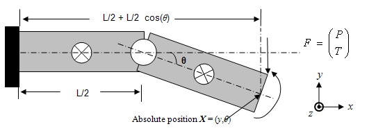
Figure 2. Generalized beam element forces and deflection.
\(P\) and \(T\) are the force and moment (torque), respectively, at the end of the GBE. The moment \(τ\) at the joint can be expressed from equation (2a) as
\[τ=k \ dθ, where \ k =(E \cdot I_{Az})/L\]
(3)
in terms of the area moment of inertia \(I_{Az}\) (second moment of area of the beam’s \(yz\) cross-section) and Young’s elastic modulus \(E\). The rotational joint \(n\) executes damped oscillations according to the normalized moment equation
\[ \ddot θ_{n}+2ξ_{0}ω_{0} \dot θ_{n}+ω_0^2θ_n=Σ_{external}^τ\]
\[ω_0^2=k/I_{Mz}\]
(4)
\(ω_0^2\) is the ratio of the effective spring constant \(k\) and the mass moment of inertia \(I_{Mz}\), both assumed to be the same for all GBEs. The damping coefficient \(2ξ_0ω_0\) that multiplies the velocity is a quasiempirical value that accounts for energy lost to viscoelastic effects.
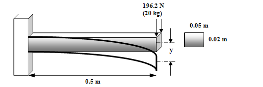
The beam is made of an aluminum alloy of density 2700 kg/m3 and Young’s modulus 6.9x10¹⁰ N/m2. We apply a load of 196.2 N (equivalent to the weight of 20 kg) to the tip.

Figure 3. Beam or cantilever bending in the xy plane.
Calculation yields these values, neglecting the beam weight.
| Mass (analytic) | 1.35 kg |
| Equilibrium deflection at tip (analytic) | -3.56 mm |
| Equilibrium deflection at tip (lumped GBEs) | -3.54 mm |
| Vibration frequency (lumped GBEs) | 63.7 Hz |
Now we apply the lumped parameter method with ten GBEs to the same cantilever, mounted to the wall with a torsional spring and including the beam weight. Again, we apply the 20 kg-mass-equivalent load to the tip. The beam bends by this load as well as by its own weight. (Bending under its own weight is a rigid body mode of the beam.) The addition of the beam weight reduces the vibration frequency considerably. This system and approximation use a model available from MATLAB Central.

| Base spring stiffness Ks | 10,000 N/m |
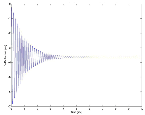
| Equilibrium deflection at tip (lumped GBEs) | -3.55 mm |
| Vibration frequency (lumped GBEs) | 6.82 Hz |

Figure 4. Motion of spring-mounted, body-loaded beam, modeled by SimMechanics with 10 GBEs.
The lumped parameter method outlined here uses purely local forces as functions of local deflections. This approximation is useful for estimating the gross behavior and endpoint deflection of the beam but not for modeling local dynamics along the beam or the beam’s vibrational modes. The restoring moment generated by bending the cantilever is proportional to its curvature. This method approximates the curvature by the local difference in slopes rather than by the correct nonlocal difference in slopes between neighboring GBEs, which cannot be represented in a series of independent elements. Thus, while the lumped parameter method is a convenient way to represent a flexible body, it does not, in general, yield correct results.
Using Finite Element Analysis Results
A more powerful approach to modeling flexible bodies in SimMechanics is to first use an FEA program to obtain the frequency or modal response of the deformed bodies and then to incorporate this response into a SimMechanics model by superimposing flexible body deflection on rigid body motion. This approach involves three steps:
- Model the flexible parts as rigid bodies using Body blocks, making sure to insert a CS at each point where you want to measure or actuate a flexible-body deflection.
- At each of these CSs, connect another Body through a Joint that includes primitives corresponding to the deflections specified in the FEA model.
These primitives are motion-actuated by a "black box" subsystem whose output is the deflection calculated from the FEA results. - Use the appropriate loads on the body as the input to this black box— the load force from one or more connected bodies or from external conditions.

Figure 5. Embedding a state-space flexible body model into a SimMechanics model.
The most direct way to implement the black box in Simulink is to use the State Space or LTI System block. Either block implements the flexible body dynamics in a state-space model and uses the results to actuate the motion of massless bodies to which other SimMechanics blocks can be connected. You can use this method to model multiple flexible bodies and complex systems comprising many flexible parts, if the deformations remain small enough for linear approximation.
The state-space model is based on the multi-DoF version of (4):
\[M \ddot q+C \dot q̇+Kq=Fu\]
with \(M,C,K\) and \(F\) as mass, friction, spring, and force matrices acting on the joint DoFs \(q\) and system inputs \(u\) (for example, reaction forces). A proper choice of coordinate transformation \(Φ\) from the spatial DoFs \(q\) to the normal coordinates \(η=Φ·q\) yields the normalized form of the dynamical equations
\[\ddot η+2Γ \dot η+Ωη=Σu \]
and diagonalizes \(Ω\), the stiffness matrix whose eigenvalues are the squared angular frequencies, \(ω_n^2.\) We obtain the \(η,Φ\) and \(Ω\) values from the FEA program. Since there is no simple way to derive \(Γ\) from theory, we use approximations and empirical values instead. In the commonly used proportional damping ansatz, Γ is assumed to be diagonal, with each eigenvalue \(γ_n = ξ_nω_n\). A complete state space also includes system outputs \(y\) (for example, sensors), represented as linear functions of the DoFs and their velocities and accelerations:
\[y=(Tq,T \dot q̇,T \ddot q).\]
We represent this collection of forced, damped, coupled linear harmonic oscillators in linear time-invariant (LTI) state-space form
\[ \dot x=Ax+Bu\]
\[y=Cx+Du\]
(5)
with
$$ x=\begin{pmatrix} η \\\dot η \\\end{pmatrix}, A=\begin{bmatrix} 0 & I\\ -Ω & -Γ\end{bmatrix}, B=\begin{bmatrix} 0 \\\ Σ \end{bmatrix}, C=\begin{bmatrix} \Theta & 0 \\ 0 & \Theta \\ -\Theta Ω & -\Theta Γ \end{bmatrix}, D=\begin{bmatrix} 0 \\ 0 \\ \Theta Σ \end{bmatrix} $$
(6)
where
\[Σ=Φ^T.F\]
and
\[Θ=Τ \cdot Φ.\]
Now we apply the FEA method to the same bending aluminum cantilever that we previously modeled using lumped parameters. Without spring-mounting at the wall or any beam weight, the lowest two vibration frequencies are 69.8 Hz and 434 Hz.
Consider this cantilever with the same spring loading and revolute joint at the wall and the same beam weight as before. Modeling the cantilever using only the lowest vibration mode in FEA yields a vibration frequency and equilibrium deflection of 8.76 Hz and -3.20 mm, respectively.
All FEA results were obtained from COSMOSWorks 2006 SP2.0, a commercial FEA software application, using default mesh parameters (global size 7.94 mm, tolerance 0.40 mm). The SimMechanics model is available from MATLAB Central.

Figure 6. Motion of spring-mounted, body-loaded beam, modeled by FEA and state space dynamics.
Comparing Methods and Results
With a reasonable number of discrete elements, the lumped parameter method gives accurate results for static bending, but the FEA method gives more accurate results for vibration modes and frequencies.
| Body-loaded, spring-mounted cantilever | Vibration frequency (Hz) | Equilibrium deflection (mm) |
|---|---|---|
| Lumped parameters (10 GBEs) | 6.79 | -3.63 |
| FEA/Frequency response | 8.76 | -3.20 |
Each method has advantages and disadvantages. The lumped parameter method is easy and quick to implement for flexible bodies with chain-like geometries but is more difficult and ambiguous, and hence less useful, for modeling bodies with higher-dimensional geometries. The simplification to independent GBEs also incorrectly represents the curvature bending moment. To correctly approximate the curvature moment you must apply the moment on each joint as a function of its own and neighboring joint deflections.
The FEA/state-space method is straightforward to implement for any body geometry and any number of DoFs. It is also more naturally suited to control design and analysis problems. Once you embed your FEA state space into a SimMechanics model, this method introduces algebraic loops as Simulink seeks a consistent solution for the acceleration of the Massless Bodies. (The acceleration depends on the reaction force, which is itself a function of the acceleration.) Algebraic loops can slow down the simulation and make it less accurate. You can break algebraic loops with Transfer Function blocks, with little or no effect on fidelity.
For a highly refined discretization and a large number of DoFs (many GBEs and joints in the lumped parameter case, many states in the FEA case) the dynamics become difficult to solve numerically.
Both methods can lead to dynamics controlled by a wide range of frequencies. A large ratio of the highest important frequency to the lowest makes the system technically "stiff" and difficult to simulate, meaning that the dynamics simultaneously reflect many different time scales. In the FEA method, you can select the modes and frequencies of interest, neglecting the others, to mitigate this difficulty.
Published 2006
References
-
Klaus-Jürgen Bathe, Finite Element Procedures. Prentice-Hall, 1996.
-
S. Crandall, D. Karnopp, E. Kurtz, and D. Pridmore-Brown, Dynamics of Mechanical and Electromechanical Systems. McGraw-Hill, 1982.
-
Michael R. Hatch, Vibration Simulation using MATLAB and ANSYS. Chapman & Hall/CRC, 2001.
-
J. N. Reddy, An Introduction to Finite Element Methods. McGraw-Hill, 1993.