SRS-Based Downlink Channel Measurements for TDD System
Channel measurements play an important role in optimizing communication performance. In time division duplexing (TDD) systems, you can utilize a sounding reference signal (SRS) for downlink channel measurements because of the channel reciprocity.
What is SRS?
SRS serves as an uplink reference signal in 5G New Radio (NR) systems, primarily used for measuring uplink channels. Although mainly intended for the uplink direction, TDD systems also utilize SRS to estimate downlink channel characteristics by exploiting the channel reciprocity principle.
While creating a base station node using the nrGNB object from the
5G Toolbox™, you can enable the TDD mode by specifying its DuplexMode property
as "TDD". To set the SRS as the downlink channel state information (CSI)
measurement signal as SRS, specify the CSIMeasurementSignalDL name-value argument of the configureScheduler
object function as "SRS".
Role of SRS in TDD Downlink Channel Measurements
Channel Reciprocity — In TDD, the downlink and uplink transmissions share the same frequency band but occur at different times. This shared frequency enables you to infer the downlink channel from the uplink channel estimate derived from SRS.
Adaptive Transmission — SRS-based downlink channel measurements enable the network to set downlink transmission parameters, such as the modulation and coding scheme (MCS), and beamforming vectors, enhancing performance and throughput.
How SRS Works in TDD Systems
A user equipment (UE) node transmits the SRS toward a 5G base station node (gNB).
The gNB node estimates the uplink channel from the SRS.
Using the reciprocity principle, the gNB node computes the downlink channel and performs channel measurements for the downlink direction.
SRS-Based Downlink Adaptive Transmission for SU-MIMO
This section discusses the SRS-based downlink adaptive transmission for single-user (SU)- multiple-input-multiple-output (MIMO) systems.
SU-MIMO System Model
A UE node transmits the SRS, denoted as x[k], to the gNB node. The representation of the received signal vector at the kth instant is:
y[k] = H x[k] + n[k],
where y[k] is an NRX-by-1 vector, x[k] is an NTX-by-1 vector, H is a matrix of size NRX-by- NTX, and n[k] is an NRX-by-1 noise vector. NTX represents the number of transmitting antennas, and NRX represents the number of receiving antennas.
When you enable sub-band measurements, you obtain a channel matrix of size NRX-by- NTX-by-NPRG, where the third dimension represents the number of precoding resource block groups (PRGs) in the carrier bandwidth. The received signal model remains the same for each PRG.
Apply Channel Reciprocity
The downlink channel matrix HDL is the transpose (or Hermitian transpose for complex signals) of the uplink channel matrix H.
Adaptive Transmission Strategy for SU-MIMO Systems
The adaptive transmission strategy for the SU-MIMO system involves these computations
Determine the maximum number of independent data streams, or maximum rank as Rmax =
min(NRX, NTX).Iteratively perform steps 3 to 5 for possible ranks starting from 1 to Rmax.
Iteratively perform steps 4 to 6 for each PRG.
Compute the zero-forcing (ZF) precoder PZF for each rank as PZF = (HDL H HDL)-1 HDLH using these steps.
Calculate the correlation coefficient matrix of the channel matrix.
Extract the lower triangular part of the correlation coefficient matrix, and take the absolute values.
Identify and sort correlation values by finding the maximum correlation value for each row and sorting the columns accordingly.
Choose the columns with the lowest correlation values, ensuring the number of selected columns equals the current rank.
Calculate the pseudo-inverse of the selected submatrix of the channel matrix.
Select the wideband MCS along with the per-PRG MCS.
Calculate the spectral efficiency for each rank using the formula SE = r × log2(M) × CR, where r is the rank of the channel, M is the modulation order, and CR is the coding rate.
Choose the rank that offers the highest spectral efficiency for downlink transmission, along with the corresponding ZF precoder and MCS.
SRS-Based Downlink Adaptive Transmission for MU-MIMO
This equation represents the signal model for a multi-user (MU)-MIMO system with a broadcast channel.
yl= Hl x+ nl, l=1,2,..,L.
Here, Hl ( l=1,2,..,L) is the NRX-by- NTX channel matrix at the lth user, nl is the thermal noise vector for the lth user, yl is the received signal vector at the lth user, and x is the transmitted vector.
Adaptive Transmission Strategy for MU-MIMO
This diagram shows an SRS-based adaptive transmission strategy for MU-MIMO.
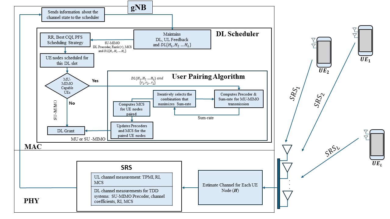
The strategy for MU-MIMO involves these operations.
Each UE node transmits the SRS.
The gNB node serving the cell estimates the UL channel (H) from the SRS.
The gNB node computes UL measurements, namely transmit precoding matrix indicator (TPMI), MCS, and rank from the channel matrix, H.
The gNB node computes the DL channel matrices (H1, H2,…, HL) using the reciprocity in TDD systems.
The gNB node sends DL channel information to the scheduler, which resides at the medium access control (MAC) layer.
The 5G scheduler has DL channel information from all the UE nodes. For m selected UE nodes (m is less than or equal to L) for that slot, based on the scheduling strategy (round-robin, proportional-fair, or best channel quality indicator), the scheduler collects the corresponding channel coefficients (DL channel from the SRS) of the selected UE nodes. It then selects the primary UE node that needs to be transmitted, and implements the determinant-based user-pairing algorithm [1] at each transmission time interval (TTI). This process involves computing the sum rate for the selected set of UE nodes after calculating the precoders using block diagonalization (BD).
For the selected UE nodes, determine the MCS by considering inter user interference to satisfy the block error rate requirement.
Note that MU-MIMO is not supported with sub-band measurements.
References
[1] Ko, Kyeongjun, and Jungwoo Lee. "Determinant-Based Multiuser MIMO Scheduling with Reduced Pilot Overhead." In 2011 IEEE 73rd Vehicular Technology Conference (VTC Spring), pp. 1-5. IEEE, 2011.